background image

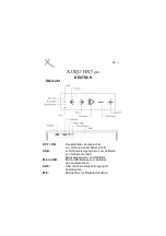
Existing drywall construction
(retrofit)

Position the template at the desired
location of the speaker. The template is
marked with both vertical and horizontal
centre lines to aid alignment.

Trace round the outer edge of the template
and cut neatly just inside the line.

To improve the mechanical integrity of the
wall and reduce the likelihood of rattles, we
recommend you apply a bead of wood glue
or mastic along the joints between the back
of the plasterboard and the studs in the
vicinity if the speaker.

Run the cable to the aperture, allowing
enough length to comfortably connect the
speaker, but not too much, as the excess
may rattle against the structure.

New drywall construction

The speaker can be installed once the wall
is completed in the same manner as
retrofitting, but it is easier to position and
cut the hole if the optional pre-mount kit is
used before the plasterboard (sheetrock) is
fitted.

Staple or nail the PMK to the studs as
described in the instructions with the kit.
Run the cable and secure it to the fixing
point on the PMK. Allow enough length to
comfortably connect the speaker, but not
too much, as the excess may rattle against
the structure.

Results are affected by how well the
plasterboard is attached to the studs and
we recommend gluing as well as screwing
or nailing the panels to the studs in the
vicinity of the speaker.

Once the board is fitted, the inner flange of
the PMK serves as a guide for a hole router
or saw.

If extra acoustic isolation to adjoining
rooms is required or some protection
against the spread of fire, use the optional
back box in place of the PMK. Follow the
instructions with the back box for fitting
and running the cable.

When fitting the plasterboard, use mastic
between the sheets and the back box to
avoid rattles. Rout or saw out the speaker
aperture using the backbox flange as a
guide. Depending on the diameter of the
router, you may need to square off the
corners with a saw.

Solid wall construction

In order for the bass performance not to be
compromised, the speaker requires a cavity
volume of at least 10 litres (0.4 cu ft). This
means that, in a standard 10cm (4 in) thick
wall, the cavity will extend beyond the
boundaries of the speaker frame. It is
possible to provide this cavity simply by
using a lintel, covering the hole with
plasterboard and fitting the speaker as
described above for retrofitting into a
drywall. (figure 6) However, the back box
provides a useful means of defining the
minimum volume required.

Follow the instructions with the back box for
fitting and running the cable. If using a wet
plaster finishing method, first paint a layer of

PVA adhesive onto the back box before
plastering to avoid rattles as a result of the
plaster shrinking away from the back box as
it dries.

If using plasterboard, stick the sheets to the
surfaces of the back box using flexible
mastic. Rout out the aperture using the
flange as a guide. Depending on the
diameter of the router, you may need to
square off the corners with a saw.

In all cases, we recommend not using
cement or mortar to fix the back box into
the brick or blockwork. rattles are best
avoided by using flexible mastic and
wedges. (figure 7)

Damping the cavity

Fill the wall cavity or back box, but not the
space immediately behind the speaker, with
unlined fibreglass or mineral wool matting.
The packing density should be just enough
to comfortably prevent the material from
dropping or sagging over time. In an open
wall cavity, fill to a distance of at least
30cm (1 ft) above and below the speaker.
(figure 8)

IMPORTANT: Ensure that the materials you
use meet local fire and safety regulations.

Fitting the speaker

All connections should be made with the
equipment switched off.

Connect the cable, observing the correct
polarity.

With the grille removed, position the
speaker in the aperture and screw in the
6 screws visible from the front. (figure 9)
These screws automatically swing out
clamping dogs that locate behind the
mounting surface. Ensure that they have
located properly before fully tightening the
screws. A certain amount of flexing of the
frame is allowed to take up unevenness in
the mounting surface, but do not
overtighten the screws as excessive
distortion of the speaker frame may result.

Customising

The frame has a paintable white semi-matte
finish, ready if necessary to be re-finished
to match your own decor. Fit the paint
mask before re-finishing. Do not re-finish
the drive units or baffle area behind the
grille. Avoid touching the drive units, as
damage may result.

Before painting the grille, peel off the fabric
scrim from the back, otherwise the pores
will get clogged and the sound will be
impaired. If the scrim does not stay in place
properly when replaced, spray the back of
the grille mesh (NOT the scrim) with a light
coating of 3M SprayMount adhesive or
similar.

Français

Garantie limitée

Cher Client, 

Bienvenue à B&W.

Ce produit a été conçu et fabriqué en vertu
des normes de qualité les plus rigoureuses.
Toutefois, en cas de problème, B&W
Loudspeakers et ses distributeurs
nationaux garantissent une main d’œuvre
(exclusions possibles) et des pièces de
rechange gratuites dans tout pays desservi
par un distributeur agréé de B&W. 

Cette garantie limitée est valide pour une
période de cinq ans à compter de la date
d’achat ou une période de deux ans pour
les composants électroniques, y compris
les haut-parleurs amplifiés. 

Conditions

1

La garantie est limitée à la réparation
de l’équipement. Les frais de transport
ou autres, les risques associés à
l’enlèvement, au transport et à
l’installation des produits ne sont pas
couverts par cette garantie. 

2

La garantie est exclusivement réservée
au propriétaire d’origine et ne peut pas
être transférée. 

3

Cette garantie ne s’applique qu’aux
produits faisant l’objet de vices de
matériaux et/ou de construction au
moment de l’achat et ne sera pas
applicable dans les cas suivants : 

a.

détériorations entraînées par une
installation, connexion ou un emballage
incorrect,

b.

détériorations entraînées par un usage
autre que l’usage correct décrit dans le
manuel de l’utilisateur, la négligence,
des modifications ou l’usage de pièces
qui ne sont pas fabriquées ou agréées
par B&W,

c.

détériorations entraînées par un
équipement auxiliaire défectueux ou
qui ne convient pas,

d.

détériorations résultant de : accidents,
foudre, eau, chaleur, guerre, troubles
de l’ordre public ou autre cause ne
relevant pas du contrôle raisonnable de
B&W ou de ses distributeurs agréés,

e.

les produits dont le numéro de série a
été modifié, effacé, éliminé ou rendu
illisible,

f.

les produits qui ont été réparés ou
modifiés par une personne non
autorisée. 

4

Cette garantie vient en complément à
toute obligation juridique nationale /
régionale des revendeurs ou
distributeurs nationaux et n’affecte pas
vos droits statutaires en tant que
client. 

Comment faire une réclamation
en vertu de la garantie

Veuillez respecter la procédure ci-dessous,
si vous souhaitez faire une réclamation
sous garantie : 

3

Summary of Contents for CWM6160

Page 1: ...Custom Inwall CWM6160 Owner s Manual and Warranty Including Back Box and PMK ...

Page 2: ...s e s r u o c 5 270mm 75mm 3 in 225mm 8 9 in 40º 60º 0 5m 20in m c 0 3 n i 2 1 m c 0 3 n i 2 1 120º 40º Figure 1 Figure 2 Figure 3 Figure 4 Figure 5 Figure 6 Figure 7 Figure 8 ...

Page 3: ...6 8 8 16 00K 69 5 2 7 2 90 90 dBSPL 45 50 50 55 55 60 60 65 65 70 70 75 75 80 80 85 85 90 90 95 95 Frequency response Polar Response Horizontal 75 60 45 30 15 0 Deg 15 30 45 60 75 Curve Freq BW Q DI 500 00 180 2 0 3 0 1 00K 180 2 0 3 0 2 00K 147 2 4 3 9 4 00K 69 5 2 7 2 8 00K 44 8 2 9 2 16 00K 69 5 2 7 2 45 50 50 55 55 60 60 65 65 70 70 75 75 80 80 85 85 90 90 95 95 dBSPL Polar Response Vertical F...

Page 4: ...s Garantia limitada 10 Manual do utilizador 10 Italiano Garanzia limitata 12 Manuale di istruzioni 12 Nederlands Beperkte garantie 13 Handleiding 14 Ελληνικά Περιορισµένη εγγύηση 15 Οδηγίες Χρήσεως 16 Русский Ограниченная гарантия 18 Руководство по эксплуатации 18 esky Záruka 20 Návod k pouãití 20 Magyar Korlátozott garancia 22 Használati útmutató 22 Polski Gwarancja 24 Instrukcja uÃytkownika 24 2...

Page 5: ...se read through this manual fully It will help you optimise the performance of the system B W distributes to over 60 countries worldwide and maintains a network of dedicated distributors who will be able to help should you have any problems your dealer cannot resolve Check the contents This pack should contain 2x wall frame baffle with drive units and crossover 2x grille with backing scrim fabric ...

Page 6: ...prevent the material from dropping or sagging over time In an open wall cavity fill to a distance of at least 30cm 1 ft above and below the speaker figure 8 IMPORTANT Ensure that the materials you use meet local fire and safety regulations Fitting the speaker All connections should be made with the equipment switched off Connect the cable observing the correct polarity With the grille removed posi...

Page 7: ... Elles ne doivent donc pas être installées à moins de 0 5 mètre d un appareil affecté par un tel champ magnétique par exemple tube cathodique d un téléviseur ou moniteur informatique Enceintes frontales audio ou Home Cinema La meilleure image stéréophonique 2 canaux sera obtenue en encastrant les enceintes approximativement à hauteur d oreille des auditeurs selon un angle compris entre 40 et 60 pa...

Page 8: ...u pour compenser des irrégularités de la surface de montage mais ne serrez pas trop les vis sous peine de déformer définitivement le châssis de l enceinte Personnalisation Le châssis est recouvert d une peinture semi mate prête à recevoir une peinture de finition adaptée à votre décoration Retirez la grille et utilisez le masque de protection pour peinture fourni avant de peindre Ne jamais tenter ...

Page 9: ...n Abschnitten können Sie Hinweise zur optimalen Positionierung entnehmen Die Rahmenbedingungen können jedoch je nach den Wohnbe dingungen variieren WARNUNG Die Lautsprecher erzeugen ein statisches Magnetfeld das sich über die Gehäusegrenzen hinaus aufbaut Daher muss zwischen Lautsprecher und Geräten die durch dieses Feld beeinflusst werden können z B Bildröhren in Fernsehgeräten Computermonitore u...

Page 10: ...sitionieren Sie den Wandrahmen ohne Abdeckung in der Öffnung und schrauben Sie die 6 von der Front aus sichtbaren Schrauben ein Figure Abb 9 Durch Anziehen dieser Schrauben werden automatisch Schnellbefestigungen hinter die Montagefläche geschoben Stellen Sie sicher dass die Schnellbefestigungen exakt ausgerichtet sind bevor Sie die Schrauben festziehen Ein gewisses Maß an Biegung des Rahmens ist ...

Page 11: ... montaje se vaya a efectuar en una pared de albañilería deberá estar preparado para construir en la misma una cavidad que se extienda más allá de los límites de la carcasa de la caja acústica ya que en caso contrario la respuesta en graves quedará seriamente comprometida Las cajas acústicas han sido equilibradas para ser montadas en el centro de cualquier pared o techo La colocación cerca de una i...

Page 12: ... definir el volumen mínimo requerido Para la colocación e instalación del cable siga las instrucciones que acompañan a la caja posterior En caso de que para el acabado utilice yeso mojado pinte en primer lugar una capa de adhesivo PVA en la caja posterior antes de enyesar con el fin de evitar que se produzcan vibraciones como consecuencia de la contracción del yeso a medida que se vaya secando En ...

Page 13: ...ipalmente para aplicações de embutir nas paredes mas poderão igualmente ser utilizadas no tecto No entanto independentemente do valor individual das colunas estas não libertarão todo o seu potencial a não ser que sejam correctamente instaladas Por favor leia este manual atentamente Pois será uma preciosa ajuda para optimizar a performance do seu sistema A B W é distribuída em mais de 60 países no ...

Page 14: ...vidade de pelo menos 10 litros 0 4 cu ft Isto significa numa parede standard de 10cm 4 in de espessura que a cavidade se estenderá para além dos limites da moldura da coluna É possível providenciar esta cavidade simplesmente através da utilização de um lintel cobrindo o buraco com pladur e colocando a coluna como descrito acima para colocação em parede falsa figura 6 No entanto a caixa traseira pr...

Page 15: ...ori prestazioni se non si effettua una corretta installazione Vi preghiamo di leggere attentamente il manuale vi aiuterà ad ottimizzare le prestazioni del sistema B W è presente in 60 paesi in tutto il mondo ed i suoi distributori nazionali saranno in grado di aiutarvi nel caso in cui doveste avere un problema che il vostro rivenditore non riesce a risolvere Controllate il contenuto L imballo dovr...

Page 16: ...iali conformi alle norme antincendio e di sicurezza in vigore nel vostro paese Fissaggio del diffusore Tutti i collegamenti dovrebbero essere effettuati con gli apparecchi spenti Collegate i cavi osservando le polarità Posizionate il pannello nella cavità senza le griglie ed avvitate le 6 viti visibili sulla parte anteriore figura 9 i ganci che bloccano il telaio sulla superficie di montaggio si p...

Page 17: ...ht mogelijk bij het centrum van het beeld te worden opgesteld Voor een center luidspreker wordt om esthetische redenen meestal de horizontale opstelling geprefereerd in welk geval moet worden gekozen voor een positie boven of onder het beeldscherm Kies de positie die het dichtst bij oorhoogte is afbeelding 2 Surround luidsprekers Monteer de luidsprekers met de tweeters ca 60 cm boven de hoogte van...

Page 18: ... Afwerking Het frame is half mat wit afgewerkt en is geschikt om gelakt te worden in een kleur die bij uw interieur past Verwijder de grill en breng het verfmasker aan voordat u aan de afwerking begint Zorg dat u de eenheden of de baffle niet mee verft Vermijd ook aanraking van de eenheden daar deze gemakkelijk beschadigd worden Voordat u de grill verft eerst de stofafdichting verwijderen daar dez...

Page 19: ... καλώδια ρεύµατος κ λπ Σε υπάρχουσες κατασκευές µε γυψοσανίδες ψευδοροφές κ λπ χρησιµοποιήστε ειδικά εργαλεία για τον εντοπισµ των πλαισίων του σκελετού σωλήνων κ λπ ώστε να τοποθετήσετε τα ηχεία στις κατάλληλες θέσεις είτε το σχέδιο της κατατοµής του ηχείου και βεβαιωθείτε τι υπάρχει αρκετ ς χώρος πίσω απ τη γυψοσανίδα ώστε οι σφιγκτήρες να µπορούν να τοποθετηθούν άνετα Αποφύγετε να τοποθετήσετε ...

Page 20: ...οιλ τητα του τοίχου στην οποία θα τοποθετηθεί το κάθε ηχείο πρέπει να έχει γκο τουλάχιστον 10 λίτρα Αυτ σηµαίνει τι σε ένα τυπικ τοίχο πάχους 10 εκατοστών η κοιλ τητα θα ξεπερνά τα ρια του πλαισίου του ηχείου Είναι δυνατ να δηµιουργήσετε αυτή την κοιλ τητα χρησιµοποιώντας απλά ένα πρέκι καλύπτοντας την τρύπα µε γυψοσανίδα και τοποθετώντας το ηχείο πως περιγράφεται πιο πάνω στην εν τητα για τις υπά...

Page 21: ...позвонить в компанию B W в Великобритании или же посетить наш вебсайт чтобы узнать контактный адрес Вашего местного дистрибьютора Для получения гарантийного обслуживания Вам необходимо предоставить данный буклет заполненный Вашим дилером и с поставленной им в день приобретения оборудования печатью или же чек продажи или другое доказательство владения оборудованием и даты приобретения Руководство п...

Page 22: ... помимо шурупов или гвоздей использовать клей После установки плиты внутренний край ПМК служит направляющей для пилы или другого режущего инструмента Если требуются звукоизоляция от соседних комнат или меры против распространения огня вместо ПМК используйте опциональный монтажный короб Следуя инструкциям на короб протяните и закрепите кабель При монтаже плиты между коробом и плитой нанесите мастик...

Page 23: ...uky Uplat ujete li reklamaci postupujte prosím dle následujících krokÅ 1 Reklamujete li v robek v zemi ve které byl i zakoupen kontaktujte autorizovaného prodejce v robkÅ B W kde jste v robek zakoupili 2 Reklamujete li v robek v jiné zemi neã ve které byl zakoupen kontaktujte dovozce kter servis zajistí P_íslu ného dovozce zjistíte bud p_ímo telefonicky u firmy B W nebo na jejich www stránkách P_i...

Page 24: ...rotáhn te kabel a zajist te ho v upev ovacích bodech PMK Nechte dostate nou délku pro pohodlné zapojení reprosoustavy nikoli v ak více aby voln kabel nezpÅsoboval rezonance uvnit_ konstrukce Nejlep ích v sledkÅ se dosáhne je li panel v okolí reprosoustavy pevn p_ichycen rouby i h_ebíky nebo p_ilepen aby nerezonoval Vnit_ní p_íruba PMK slouãí jako vodítko pro vy_íznutí i vyfrézování otvoru do p_ipr...

Page 25: ...i John Bowers ihlette aki szerint nem csak az audio technológiában és a fejlesztésében történµ komoly mérték befektetés fontos hanem megbecsülése a zenének és a filmeknek is ezzel biztosítván a technika maximális hatékonyságát A CWM hangsugárzók melyet a mennyezetbe vagy akár falba történµ beépítésre terveztek 2 csatornás sztereó vagy házimozi használathoz Azonban függetlenül attól milyen kiválóak...

Page 26: ... falba történµ beépítés Hogy a mélyhang teljesítmény optimális legyen a hangsugárzó kb 10 literes üreget igényel Egy 10cm es vastagságú fal esetén az üreg túl fog nyúlni a hangsugárzó keretén Amennyiben lehetséges egyszer en nyílásáthidalás segítségével a lyukat eltakarva egy gipszkartonnal helyezze el a hangsugárzót az elµbbi fejezetekben leírtan 6 ábra Azonban hátsó doboz használata is lehetsége...

Page 27: ...e zostanƒ w a ciwie zamontowane Prosimy o uwaÃne przeczytanie tej instrukcji PomoÃe ona zoptymalizowaπ parametry brzmieniowe ca ego systemu B W dostarcza swoje produkty do ponad 60 krajów na ca ym wiecie utrzymujƒc sieπ specjalizowanych dystrybutorów którzy sƒ w stanie pomóc w rozwiƒzaniu jakichkolwiek problemów z którymi nie moÃe poradziπ sobie Twój sprzedawca SprawdØ zawarto π Kartonowe opakowan...

Page 28: ...k wymaga komory o obj to ci nie mniejszej nià 10 litrów Oznacza to Ãe w przypadku standardowej ciany o grubo ci 10 cm komora w której pracuje g o nik musi mieπ powierzchni wykraczajƒcƒ rozmiarem poza kraw dzie ramki MoÃliwe jest uzyskanie takiej obj to ci poprzez zastosowanie nadproÃa przykrycie otworu p ytƒ gipsowo kartonowƒ i zamocowanie g o nika w analogiczny sposób jak ma to miejsce przypadku ...

Page 29: ...26 ...

Page 30: ...27 ...

Page 31: ...28 ...

Page 32: ...wall speaker system 1x 25mm 1in high frequency 1x 165mm 6 5 in woven fibreglass mid bass 6dB at 40Hz and 22kHz 50Hz 20kHz 3dB 89dB spl 2 83V 1m 8Ω minimum 4 3Ω 3 2kHz 20W 130W continuous into 8Ω on unclipped programme Height 310 12 2in Width 216 8 5in Height 280mm 11in Width 188mm 7 4in 89mm 3 5in from ceiling surface 1 6kg 3 5lb PMK650 89mm 3 5in 3 5mm 0 1in 216mm 8 5in 310mm 12 2in 280mm 11 0in ...

Page 33: ......

Page 34: ...400mm 15 7in 340mm 13 4in ...

Page 35: ......

Page 36: ......

Page 37: ...les bwgroup com B W Group North America T 1 978 664 2870 E marketing bwgroupusa com B W Group Asia Ltd T 852 2 869 9916 E showroom bwgroup hk B W Group Ltd Dale Road Worthing West Sussex BN11 2BH England T 44 0 1903 221800 F 44 0 1903 221801 info bwgroup com www bwgroup com II09971 Issue 2 ...

Reviews: