37355-0-0217
Page 25
UTILITY INSTALLATION (CONT'D)
JUNCTION BOX WIRING INSTALLATION
A factory-installed junction box is located at the lower left corner
inside the firebox. For 120V electrical requirements install the
electrical receptacles into the junction box.
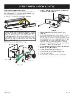
1. Remove burner box from fireplace.
See Figure 37.
Figure 37
All wiring must be done by a qualified electrician and shall be in
compliance with all local, city and state building codes. Before
making the electrical connection, make sure the main power
supply is disconnected. The fireplace, when installed, must be
electrically grounded in accordance with local codes or, in the
absence of local codes, with the National Electrical Code ANSI/
NFPA 70 (latest edition).
NOTICE:
Observe orientation of snap-in plug.
JUNCTION BOX
WHITE
WIRE NUT
GROUND
BLACK
COVER PLATE
SNAP-IN
RECEPTACLE
ACCESS PLATE
120V POWER
SUPPLY
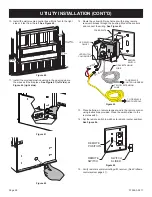
Figure 38
2. Remove the
electrical access cover panel from the left end
of the fireplace.
See Figure 39.
Figure 39
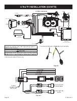
3. Snap in the receptacles to the cover plate as shown in
Figure 38.
4. Run 14/2 NM-B with ground or 12/2 NM-B with ground wire
through the electrical access panel into the Junction box.
Secure wiring with the wire connector as required and install
the two receptacles as shown in
Figure 38.
Attach the black
wires with a wire nut, and the white wires with a wire nut.
Secure the incoming ground wire and green receptacle
ground wires under the green ground screw provided in the
junction box. Install the Junction box cover.
5. Re-install the junction box into the firebox using the screws
removed in step 2.
See Figure 39.
6. Connect flexline in burner box to inlet gas line.
7. Re-install burner box with screws removed earlier.
8. Check gas lines for leaks.
9 Plug AC adapter and LED transformer to junction box.


