


37355-0-0217
Page 23
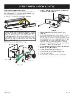
UTILITY INSTALLATION
Bring the gas supply through the left side of the fireplace to
connect to the burner.
See Figures 33 and 34.
Consult the
current National Fuel Gas Code, ANSI Z223.1 CAN/CGA-B149
(.1 or .2) installation code.
RECOMMENDED GAS PIPE DIAMETER
Pipe Length
(Dimensions
in feet)
Schedule 40 Pipe
Inside Diameter
Tubing, Type L
Outside Diameter
(Dimensions in Inches)
NAT
LP
NAT
LP
0-10
1/2
3/8
1/2
3/8
11-40
1/2
1/2
5/8
1/2
41-100
1/2
1/2
3/4
1/2
101-150
3/4
1/2
7/8
3/4
CAUTION
Never use plastic pipe. Check to confirm whether your local
codes allow copper or galvanized tubing.
NOTICE:
Since some municipalities have additional local codes, it
is always best to consult your local authority and installation code.
The use of the following gas connectors is recommended:
— ANSI Z21.24 Fireplace Connectors of Corrugated Metal
Tubing and Fittings.
— ANSI Z21.45 Assembled Flexible Fireplace Connectors of
Other Than All-Metal Construction
The above connectors may be used if acceptable by the authority
having jurisdiction. The Commonwealth of Massachusetts
requires that a flexible fireplace connector cannot exceed three
feet in length.
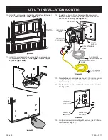
TEE HANDLE
FLEX TUBING
FLARE FITTING
FLEXIBLE GAS LINE CONNECTION
GAS SUPPLY
Figure 33
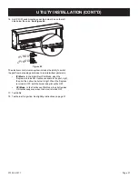
INSTALLING THE MAIN GAS SHUT-OFF
Each fireplace should have its own manual gas shut-off.
Locate the manual main gas shut-off in the vicinity of the fireplace
easily accessible after assembly. Contact your local authorized
installer for installation or relocation when no shutoff exists or the
location is not adequate.
Compounds used on threaded joints of gas piping are resistant
to the action of liquefied petroleum gases. Gas lines must be
checked for leaks by the installer. A leak testing solution or soap
should be used for testing leaks on all exposed connections.
After testing is complete, all solutions should be cleaned off.
On unexposed connections, a pressure test should be made.
Never use an exposed flame to check for leaks. Fireplace must
be disconnected from piping at inlet of control valve and pipe
capped or plugged for pressure test. Never pressure test with
fireplace connected; control valve will sustain damage.
When using copper or flex connector use only approved fittings.
The fireplace and its individual shut-off valve must be
disconnected from supply piping system during any pressure
testing of that system at test pressures in excess of 1/2 psig
(3.5kPa).
The fireplace must be isolated from the gas supply piping
system by closing its individual manual shut-off valve during any
pressure testing of the gas supply piping system at test pressures
equal to or less than 1/2 psig (3.5kPa).
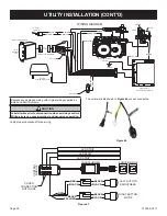
TESTING GAS SUPPLY PRESSURE
NOTICE:
The gas controls are equipped with a captured screw-
type pressure test point. It is not necessary to provide a 1/8-inch
test point up stream of the control.
Natural gas will have a manifold pressure approximately 10.0
inches w.c. at the pressure regulator outlet wit the inlet pressure
to the pressure regulator from a minimum of 11.0 inches w.c. for
the purpose of input adjustment to a maximum of 13.0 inches w.c.
A test gage connection is located on the gas valve for measuring
gas pressure. The connections are two contained screws inside
tapered hose slip connections.
GAS PRESSURE (Inches Water Column)
Gas Type
Maximum
Minimum
Manifold
NAT
10.5
7.0
3.5
LP
13.0
11.0
10.0
MANIFOLD PRESSURE
TEST PORT
OUT
INLET PRESSURE
TEST PORT
IN
Figure 34
WARNING
If one of the procedures results in pressures in excess of
1/2 psig (14 inches w.c.) (3.5 kPa) on the fireplace gas
valve, it will result in a hazardous condition.


