WASP™ NEST4 Smart Receiver and Gateway Operations Manual
- 6 -
The technician must ensure proper mounting of antenna to meet certification requirements of
installation site.
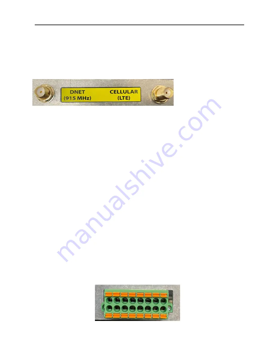
To attach the antenna, carefully screw the antenna cable to the SMA connection at the base of
the BossPac NEST™ Receiver Gateway. See photo below. Attach antenna to opposite end of
cable, (N type connector).
2.3.3 Attaching the LTE Antenna
Figure 1: Antenna Connections
WARNING – EXPLOSION HAZARD. DO NOT CONNECT OR DISCONNECT THE ANTENNA IN A
HAZARDOUS ENVIRONMENT.
AVERTISSEMENT – RISQUE D’EXPLOSION. NE PAS BRANCHER OU D
Ѐ
-BRANCHER L’ANTENNE
DANS UN ENVIRONMENT FLAMMABLE.
2.3.4 Wiring NEST Circuit Board
The rear cover, (backplate), needs to be removed to access the following connections: USB and
SD Card connections.
2.3.5 Circuit Board Terminal Block
The NEST circuit board has a 16-pin terminal block. A diagram of the terminal block is shown
below.
Pin 1 and Pin 2
are differential analogs inputs.
Pin 3
is a digital input.
Pin 4
is an analog output.
Pin 5 and Pin 7
are analog inputs.
Pin 6
can be configured as a digital input or output.
Pin 8
is a digital output.
Pin 13 and Pin 14
are assigned for MODBUS connections.
Pin 15(+5V to 24V) and Pin 16(GND)
are the power connections. The NEST Receiver must be
powered with a
Class 2
power supply providing an input voltage between 5 VDC to 24 VDC
Pins 9, 10, 11 and 12
are used for 4-wire serial connections.
1 3 5 7 9 11
13 15
2 4 6 8 10 12 14 16


