Installation and User Guide |
VIP XD
EN
| 76
Appendix
Bosch Security Systems | 2005-05 | V1.0
Terminal block
The terminal block is used to connect external signal sources or alarm switches,
as a relay output, a serial interface or as a power supply.
Options for using the serial interface include transparent data transmission and
operation of the unit with a terminal program. Depending on the setting, the
serial interface uses the RS232 or RS244/285 standards. The standard used
depends on the current configuration (see pages 41 and 55).
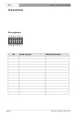
Pin assignment
The pin assignment for the serial interface depends on the standard used.
To operate the alarm inputs connect each alarm input to a ground contact (GND)
via a trigger contact.
Pin
RS232 standard
RS422/485 standard
IN1
Alarm input 1
Alarm input 1
IN2
Alarm input 2
Alarm input 2
IN3
Alarm input 3
Alarm input 3
IN4
Alarm input 4
Alarm input 4
GND
GND (ground)
GND (ground)
GND
GND (ground)
GND (ground)
R (top)
Relay
Relay
R (bottom)
Relay
Relay
CTS
CTS (clear to send)
RxD- (receive data minus)
RTS
RTS (ready to send)
TxD- (transmit data minus)
RXD
RxD (receive data)
RxD+ (receive data plus)
TXD
TxD (transmit data)
TxD+ (transmit data plus)
+
12 V (power supply)
12 V (power supply)
–
GND (ground)
GND (ground)

