background image

VG5 600 Series AutoDome Audio

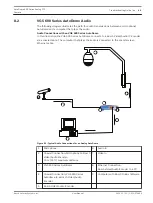
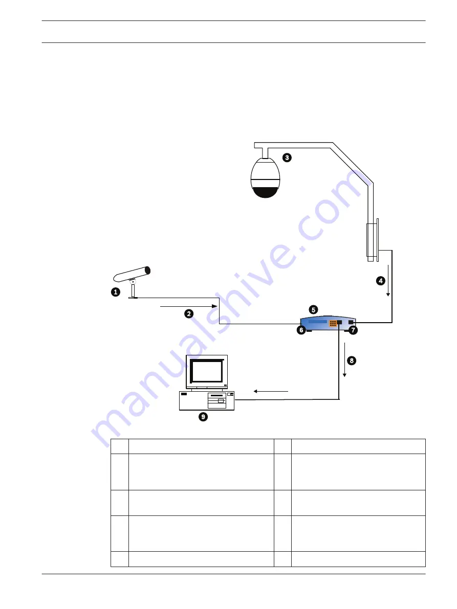
The following diagram illustrates the path for audio transmissions between a microphone/
AutoDome and a computer that plays the audio.
Audio Connections with an VG5 600 Series AutoDome
In this illustration the VG5 600 Series AutoDome connects to a Bosch Video/Audio IP Encoder
via a coaxial cable. The computer that plays the audio is connected to the encoder via an
Ethernet cable.

Figure 8.1: Typical Audio Connections for an Analog AutoDome

1

Microphone

6

Audio In

2

Coaxial Connection; Microphone to Bosch
Video/Audio Encoder;
10 m (33 ft) maximum distance

7

Video In

3

VG5 600 Series AutoDome

8

Ethernet Connection;
Bosch Video/Audio Encoder to a PC

4

Coaxial Connection; VG5 600 Series
Autodome to a Bosch Video/Audio
Encoder

9

Computer with Bosch DiBos Software

5

Bosch Video/Audio Encoder


8.2

AutoDome 600 Series Analog PTZ
Camera

Troubleshooting Guide | en

65

Bosch Security Systems, Inc.

User Manual

2014.11 | 2.1 | F.01U.270.005

Summary of Contents for VG5 600 Series

Page 1: ...AutoDome 600 Series Analog PTZ Camera VG5 600 Series en User Manual ...

Page 2: ......

Page 3: ...AutoDome User Commands unlocked 28 3 1 Setting AutoPan Mode 28 3 2 Setting Preset Shots 28 3 3 Specifying a Shot or a Sector Title 28 3 4 Configuring Preposition Tours 29 3 5 Programming the Inactivity Operation 29 3 6 Recording Tours 30 4 Alternative Control Protocols 31 4 1 Setting FastAddress with Alternative Protocols 31 4 1 1 Using an American Dynamics Controller 31 4 1 2 Using a Pelco Contro...

Page 4: ...zation 57 7 7 Pre position Tour 57 7 8 Azimuth Elevation and Compass Directions 57 7 8 1 Setting the Azimuth Zero Point 58 7 8 2 Displaying Azimuth Elevation and Compass Headings 59 7 9 AutoHome Recalibration Commands and Settings 59 7 9 1 AutoHome Recalibration Operation 60 7 9 2 Using the AutoHome Recalibration 60 8 Troubleshooting Guide 62 8 1 VG5 AutoDome Operation and Control 62 8 2 VG5 600 S...

Page 5: ...d right and tilts up and down It also adjusts the lens focus The entire homing phase lasts approximately 40 seconds and ends with a firmware version screen Bosch Security Sys AutoDome r 600 Series Day Night 36X SC Boot FPGA VCA_boot STD Comm No Heater FastAddress Not Set 5 00 00 03 1 05 00 02 1 00 00 00 5 00 00 03 1 13 01 05 1 02 00 01 Figure 1 1 Sample VG5 Startup Firmware Version Screen The spla...

Page 6: ...s a selection Focus Key Sets the lens focus or makes a menu selection in OSD mode Iris Key Sets the lens iris setting or makes a menu selection in OSD mode Key LEDs Indicates an active key LCD Displays the current status Joystick Controls a pan tilt zoom PTZ AutoDome camera Table 1 1 Typical Keyboard Functions Dome Operation How to control To Pan Side to Side Move the joystick left or right To Til...

Page 7: ...ithout an address in the system Notice If a keyboard is set to a camera number that already has an address that camera also responds to this command ON 998 ENTER Displays and programs all cameras with or without an address in the system ON 997 ENTER Displays the current address status of all cameras in the system simultaneously To set an address for a camera without an address 1 Select the camera ...

Page 8: ...ables security and requires a user to enter the unlock command OFF 90 ENTER before invoking a locked command 9999 Disables all security and allows all users to access locked commands To set or change a password locked command 1 Press OFF 90 ENTER to turn off the command lock 2 Press SET 802 ENTER to access the password menu 3 Tilt the joystick up or down to choose a number Tilt the joystick right ...

Page 9: ...ock To open the main Setup Menu locked command 1 Press OFF 90 ENTER to turn off the command lock 2 Press ON 46 ENTER to access the Main Menu 3 Use the joystick to highlight a menu item 4 Press Focus Iris to open a menu 5 Follow the on screen instructions Notice The AutoDome displays only those menus applicable to the particular AutoDome Series configuration Use the joystick to navigate through the...

Page 10: ...he alarm settings such as inputs outputs and rules Language Displays the language Advanced Accesses the advanced features menu including Stabilization AutoTrack Sensitivity Camera Height and Virtual Masking Diagnostics Displays the status of diagnostic events Notice To select the Exit Menu item from anywhere in the current menu use the Zoom command Camera Setup Menu The Camera Setup Menu provides ...

Page 11: ...ical indoor conditions Outdoor W B Optimizes camera color for typical outdoor conditions AWB Hold Sets the camera s color settings for the current scene Manual Allows a user to adjust the Red and Blue gain Sliding scale 1 to 100 Outdoor Auto Automatically adjusts the white balance to reduce the dark tones at dawn or dusk Sodium Lamp Optimizes the sodium vapor light to restore objects to their orig...

Page 12: ...e feature on or off ON OFF or Auto OFF Shutter Mode Turns Auto SensUP on or off Auto SensUP or OFF Auto SensUP Shutter Adjusts the electronic shutter speed AES Sliding scale 60 at extreme left to 1 10000 1 60 sec NTSC or 1 50 sec PAL Auto SensUP Max Sets the limit for sensitivity when the shutter speed is set to Auto SensUP 15x 7 5x 4x or 2x 15x Night Mode Selects night mode B W to enhance lightin...

Page 13: ...creen CONSTANT Auto Focus is always active even while the camera is moving MANUAL Auto Focus is inactive manual focus must be used SPOT The camera activates Auto Focus after the camera stops movement Once focused Auto Focus is inactive until the camera moves again SPOT Auto Iris Automatically adjusts to varying light conditions MANUAL Iris must be adjusted manually CONSTANT Auto Iris is constantly...

Page 14: ...erisk are the default settings PTZ Setup Exit Autopan 30 deg sec Tour 1 Period 5 sec Tour 2 Period 5 sec PTZ Fixed Speed 4 Inactivity OFF Inact Period 2 min AutoPivot ON AutoDome Orientation NORMAL Freeze Frame on Preposition ON Tilt Up Limit Restore Defaults Factory Setting Focus Iris Select PTZ Menu Choices Menu Description Sub menu Description Default Setting Exit Exits the menu AutoPan Adjusts...

Page 15: ... Automatically rotates the camera 180º when following a subject traveling directly beneath the camera OFF or ON ON AutoDome Orientation Automatically rotates the video 180º INVERTED or NORMAL NORMAL Freeze Frame On Preposition Holds a preposition video frame while moving to another preposition OFF or ON ON Tilt Up Limit Sets the upper tilt limit of the camera Use joystick to move to a scene Azimut...

Page 16: ... Titles are displayed for a few seconds then disappear from the screen MOMENTARY Camera OSD Controls how the OSD displays camera response information such as Digital Zoom Iris open close and Focus near far OFF or ON ON Display Adjust Adjusts the text brightness and vertical position of the on screen title Exit Exits the menu Up Moves screen title up Down Moves screen title down Brighter Brightens ...

Page 17: ...tructions to set a mask See Alarm Rules page 49 Restore Defaults Restores the default settings for this menu only Edit Sector Title Allows editing existing Sector Zone Titles Select a sector title to access the character palette See Specifying a Shot or a Sector Title page 28 for instructions Edit Scene Title Allows editing existing Scene Shot Titles Select a scene title then choose a menu option ...

Page 18: ...ally sets the baud rate when AutoBaud is set to OFF Choices are 2400 4800 9600 19200 38400 and 57600 Then follow the OSD to confirm the selection 9600 Bilinx Turns on Bilinx control communication Only available when not connected to a Bilinx data interface unit Toggles ON or OFF ON Alarm I O Setup The Alarm Setup Menu provides access to the Alarm I O Setup Menu to establish the alarm inputs and ou...

Page 19: ...s 1 7 Defines the type of physical input N O Normally open dry contact N C Normally closed dry contact N C S Normally closed supervised contact N O S Normally open supervised contact N O Inputs 8 12 Defines input commands that can be used in a rule Command inputs can also be customized by using non assigned keyboard command numbers NONE No command defined Aux On Responds to a standard or custom ke...

Page 20: ...Outputs 6 Aux On 1 7 Aux Off 8 8 Shot 99 9 OSD 10 Transmit 11 NONE 12 NONE Focus Iris Select Type Right Left Select Mode Outputs Setup Menu Choices Menu Description Sub menu Description Default Setting Exit Saves and exits the menu Outputs Setup Defines physical outputs and keyboard commands for use in a rule Outputs 1 3 Defines a physical output N O Normally open circuit N C Normally closed circu...

Page 21: ...u shows the status of the rules and lets you add new rules or modify an existing rule The default setting is Empty Notice You can program a total of twelve rules You must define the inputs and outputs before you program a rule See Alarm I O Setup page 18 to configure alarm inputs and outputs Rule Setup Rule 1 Exit Exit 1 Rule 1 Enabled Enabled YES 2 Rule 2 Disable d Input 3 Rule 3 Invalid NONE 4 R...

Page 22: ...on Default Setting Exit Saves and exits the menu Enabled Turns the rule on or off after its inputs and outputs have been defined YES to enable or NO to disable NO Input Toggles through a list of valid inputs set in the Alarm I O Setup Inputs Setup Menu that define the rule s inputs A rule can have up to four 4 inputs Alarm Inputs 1 7 and any additional inputs which were set in the Inputs Setup Men...

Page 23: ... Choices Menu Description Default Setting Exit Saves and exits the menu Choose a language Select a language in which the system displays the on screen menus Advanced Feature Setup Menu The Advanced Menu provides access to the Advanced Features Setup menus such as image Stabilization AutoTrack Sensitivity and Virtual Masking Menu items marked with an asterisk are the default settings Advanced Featu...

Page 24: ...toTrack Timeout feature When On AutoTrack gives up after the Timeout Period if tracking in a confined area for example a tree a flag etc OFF AutoTrack Timeout Period Enters the AutoTrack Timeout Period set menu Sliding scale 30 sec 1 to 30 min 5 min Camera Height Defines the height of the camera for AutoTrack A range from 2 4 m 8 ft to 30 7 m 100 ft 3 6 m 12 ft Virtual Masking Enters the Virtual M...

Page 25: ...ow Volt Events 0 Power Up Events 0 Video Loss Events 0 Total Time On 0hr 0min Focus Iris Save and Exit Diagnostic Events Menu Description Sub menu Description Exit Saves and exits the menu Alarm Status Enters the Alarm Status menu and displays the real time status of alarm inputs and outputs Alarm Inputs 1 to 7 Alarm Outputs 1 to 3 and Alarm Relay AutoDome 600 Series Analog PTZ Camera On Screen Di...

Page 26: ...enu is unlocked CTFID Access Displays the number of times the Configuration Tool is accessed Homing Events Displays the number of times the AutoDome was rebooted Homing Failed Displays the number of times the AutoDome failed to home properly Loss Home Events Displays the number of times the AutoDome lost the home position Home Position Good Displays if the current AutoDome home position is good Di...

Page 27: ...s Save and Exit Menu Description Options Exit Saves and exits the menu Alarm Input 1 7 Displays the status of alarm inputs 1 through 7 High Low Open Normally Open Closed Normally Closed Alarm Output Displays the status of the alarm output AutoDome 600 Series Analog PTZ Camera On Screen Display Menu Navigation en 27 Bosch Security Systems Inc User Manual 2014 11 2 1 F 01U 270 005 ...

Page 28: ...a title for the shot see the procedure below To view a Shot 4 Press SHOT ENTER where is the number of the scene position you want to view To store or clear a Shot 1 Press SET 100 ENTER to access the Store Clear Scene Menu 2 Follow the on screen instructions To disable overwrite confirmations If you overwrite a preset shot the AutoDome issues a confirmation message prompting you approve the overwri...

Page 29: ...ove Scenes Menu 2 Use the Focus Iris buttons to add or remove the selected scene from the tour To start custom Preposition Tour 2 4 Press ON 7 ENTER to start a tour The tour cycles through the series of shots in the order they were defined until it is stopped To edit a custom Preposition Tour 2 1 Press SET 900 ENTER to access the Add Remove Menu 2 Press the Focus Iris buttons to add or remove the ...

Page 30: ...ur A 1 Press ON 100 ENTER to start recording a tour 2 Press OFF 100 ENTER to stop recording To playback Recorded Tour A 1 Press ON 50 ENTER to begin continuous playback 2 Press OFF 50 ENTER or move the joystick to stop playback To Record Tour B 1 Press ON 101 ENTER to start recording the tour 2 Press OFF 101 ENTER to stop the tour To playback Recorded Tour B 1 Press ON 52 ENTER to begin continuous...

Page 31: ... remember that some American Dynamics Manchester systems use address blocks of 1 to 64 while American Dynamics Sensormatic systems typically use address blocks of 1 to 99 meaning that when the controller keyboard displays video for cameras higher than 64 or 99 the keyboard controller sends a different control code to the camera see Appendix FastAddress Conversions page 66 for conversion charts For...

Page 32: ...the VG4 AutoDome See example as follows Enter FastAddress FastAddress Not Set Unique Identifier 200668 000000 r Continue Exit Joystick Match Identifier Move the joystick up or down to select the individual number Move the joystick right to move to the next FastAddress number position When completed the FastAddress number entered must match the Unique Identifier displayed See example as follows Ent...

Page 33: ... Address sent by the controller and is displayed as Save as FastAddress is based on either 1 64 AD Manchester or 1 99 AD Sensormatic RS 422 It is NOT POSSIBLE to change the address that is displayed The following options are available 2 Press the FOCUS or the IRIS button to store the FastAddress number Move the joystick to highlight Clear Current FastAddress and then press the FOCUS or the IRIS bu...

Page 34: ...with the new Fast Address displayed Move the joystick to highlight EXIT and then press FOCUS or IRIS to exit the menus New Fast Address Saved Setup Menu Exit Command Lock OFF Bosch Menu Camera Setup PTZ Setup Edit Password FastAddress 3 Software Version Ack and Reset Alarms Restore All Settings 34 en Alternative Control Protocols AutoDome 600 Series Analog PTZ Camera 2014 11 2 1 F 01U 270 005 User...

Page 35: ...on to open the menu 5 Use the joystick to enter the unique identifier for the VG4 AutoDome 6 Move the joystick up or down to select the number Move the joystick right to move to the next number position 7 Move the joystick right to select Continue Then press the FOCUS or the IRIS button 8 Use the keyboard to enter the FastAddress number Then press the Camera button Note You must first clear an ass...

Page 36: ...board inputs with the following convention 1 a Command Number and 2 a Function key input The AutoDome uses the PRESET command key to save and recall presets pre positions 1 through 99 Notice To save a preset enter the desired number and hold the PRESET key for approximately two 2 seconds To recall a preset enter the desired preset number or command and momentarily press and release the PRESET key ...

Page 37: ...al home position 80 PRESET Toggles the Synchronization Mode between Line Lock and Internal Pelco Frame Scan This command is available if commands are unlocked using the Main menu 81 PRESET Initiates Preset Tour 1 82 PRESET Initiates Preset Tour 2 92 PRESET Sets the Left pan limit for an AutoScan with Limit Stops enabled 93 PRESET Sets the Right pan limit for an AutoScan with Limit Stops enabled 94...

Page 38: ... the preset command numbers Consult the specific Pelco controller s documentation for supported preset commands 38 en Alternative Control Protocols AutoDome 600 Series Analog PTZ Camera 2014 11 2 1 F 01U 270 005 User Manual Bosch Security Systems Inc ...

Page 39: ... Press 95 PRESET press the PRESET button for approximately 2 seconds to open 2 Use the joystick to highlight a menu item 3 Press either the Focus or the Iris key to open a menu item 4 Follow the on screen instructions at the bottom of the screen Setup Menu Exit Command Lock OFF Bosch Menu Camera Setup PTZ Setup Edit Password FastAddress Not Set Advanced Software Version Ack and Reset Alarms Restor...

Page 40: ...to their original default setting Reset All Memory locked Clears all settings including scene shots tours and recordings stored in the AutoDome memory Notice After a period of 4 5 minutes of inactivity the OSD menu times out and exits without warning Some unsaved settings can be lost Command Lock locked The Pelco Command Lock Menu allows or prohibits the use of locked commands The default setting ...

Page 41: ...ings Diagnostics Reset All Memory Factory Setting Focus Iris Select Focus Iris Select Refer to Section 2 On Screen Display Menu Navigation for a complete description of Bosch menus and configuration settings Camera Setup unlocked The Pelco Camera Setup Menu provides access to camera settings Camera Setup Exit White Bal OUTDOOR Night Mode AUTO AutoDome 600 Series Analog PTZ Camera Pelco On Screen M...

Page 42: ...hes from color to monochrome ON Sets Night Mode on OFF Sets Night Mode off AUTO Sets Night Mode to Auto set ON Day Night models only PTZ Setup unlocked The Pelco PTZ Setup Menu provides access to the PTZ settings such as tours scan speed presets limit stops recording and AutoPivot PTZ Setup Exit Edit Tour 1 Edit Tour 2 Tour 1 Period 5 sec Tour 2 Period 5 sec Scan Speed 30 deg sec Edit Presets Limi...

Page 43: ...c 30 sec Edit Presets Modifies preset scenes 1 99 scenes Limit Stops Toggles the Limit Stops for AutoScan ON or OFF OFF Recordings Selects record Pattern 1 or 2 if normal pattern command does not respond A or B A AutoPivot Follows a subject while beneath the camera without inverting the picture ON or OFF ON Other Menus Menu Description Default Setting Edit Password Sets or displays the password Se...

Page 44: ...efault settings Reset All Memory locked Restores all settings to their original factory default settings and clears all user programmed settings such as preset scenes and recordings 44 en Pelco On Screen Menus AutoDome 600 Series Analog PTZ Camera 2014 11 2 1 F 01U 270 005 User Manual Bosch Security Systems Inc ...

Page 45: ...tter Speed slide bar On Off 24 Stabilization Electronic Stabilization On Off 26 Wide Dynamic Range Activate Deactivate On Off 35 White Balance Mode Enters White Balance menu On 40 Restore Camera Settings Restores all setting to their original defaults On Off 41 Line Lock Phase Adjust Enters delay adjustment slide bar On Off 42 Sync Mode On Line Lock Off Internal On Off 43 Auto Gain Control AGC On ...

Page 46: ...rsion number On Off 69 Alarm Rule Activation Deactivation On Enables all alarm rules Off Disables all alarm rules On 72 Re initialize Camera Performs camera lens re initialization functions On Off 78 AutoTrack Turns AutoTrack on or off On 79 Camera Height Enters the Camera Height menu On Off 80 Digital Zoom Lock Turns digital zoom on and off On Off 81 Alarm Output 1 Open Collector On Activates out...

Page 47: ... Hides compass heading Refer to Azimuth Elevation and Compass Directions page 57 On 99 Factory P T Home Position Recalibrates home position can be used as an Alarm Output On Off 100 Record A Activate Deactivate On Off 101 Record B Activate Deactivate On 997 FastAddress display Display current address On 998 FastAddress all units Display and program current address On 999 FastAddress unaddressed do...

Page 48: ...rval by 6 hours Each Off decreases interval by 6 hours On Off 684 Initial Offset Time Sets the initial offset time for the recalibration interval The offset time starts after the Homing Calibration is enabled The recalibration interval begins its countdown after the offset time Each On increases offset time by 4 hours Each Off decreases offset time by 4 hours Note The offset time does not take eff...

Page 49: ...m before the rule is disabled Prevents the modification of an alarm rule while disabled Alarm Rule Examples Following are three examples for setting up alarm rules The first example is a basic alarm rule and the second and third examples are more complex Example 1 Basic Alarm Rule Scenario We want a door alarm contact to 1 Flash an OSD message ALARM 1 on the display when the alarm is triggered 2 M...

Page 50: ...n AutoTrack 4 Transmit a Bilinx signal to the head end system to trigger an alarm response The sequence to program this alarm rule example is as follows 1 Wire and set the alarm Input s 2 Wire the motion detector to Input 1 This circuit is normally open Wire the gate alarm contact to Input 5 This circuit is normally closed Notice For instruction on wiring alarm and relay connections see the AutoDo...

Page 51: ...fter an alarm is triggered This example uses the Configuration Tool for Imaging Devices CTFID software tool Refer to the Configuration Tool for Imaging Devices User Guide available at www boschsecurity com 4 Launch the CTFID software from a computer that is connected to a VG5 AutoDome Figure 7 1 CTFID Overview Window 4 Click the Online Config button and then expand Alarm Figure 7 2 Expanded Alarm ...

Page 52: ...ick Alarm Rule 1 2 Click the Yes radio button to enable the rule 3 Type the number 1 or use the slider bar to select 1 for the Input option 4 Select Alarm Input 1 from the Input Option drop down list 5 Ensure that the Output number is set to 1 6 Select Shot 1 from the Output Options drop down list This option instructs the AutoDome to move to pre position shot 1 when Input 1 is true 52 en Advanced...

Page 53: ...n The AutoDome features enhanced AutoTrack software with more versatility and smoother object tracking AutoTrack continuously follows an individual even if the person passes behind a Privacy Mask When used with Virtual Mask it is able to ignore predefined areas of background motion You can manually start AutoTrack or program the AutoDome to automatically turn on AutoTrack Manual Enter the keyboard...

Page 54: ...g angle and unwanted motion from trees for example may interfere with AutoTrack operation Use the following recommendations to ensure smooth AutoTrack operation Mount Mounting Surface Stability Mount the camera in the most stable position Avoid locations affected by vibrations such as those caused by a roof top air conditioner These vibrations may cause complications when the camera zooms in on a ...

Page 55: ...he joystick to highlight the Advanced menu 4 Select the AutoTrack Sensitivity option and change the parameter to Auto or to a value between 1 10 5 Exit the AutoTrack Sensitivity menu Then exit the Advanced Feature Setup menu 6 Access the PTZ Setup menu 7 Select the AutoPan option and change the parameter to one of the suggested values in the table above 8 Exit the AutoPan menu Then exit the PTZ Se...

Page 56: ...n Detection with Region of Interest Preset positions 90 through 99 With the VG5 Series AutoDome the motion detection software can be configured to create a Region of Interest within multiple preset positions or scenes It can take advantage of Virtual Masking to ignore motion in predefined areas Motion Detection can also be used as an Alarm Rule input Preset positions 90 through 99 are reserved for...

Page 57: ...ard command SHOT 900 ENTER and follow the on screen instructions Tour 2 is a customizable tour that allows you to rearrange the sequence of scenes on the tour by inserting and deleting scenes To enter the Edit Tour 2 menu enter the keyboard command SET 900 ENTER and follow the on screen instructions Azimuth Elevation and Compass Directions The VG5 AutoDome allows a user to display the azimuth and ...

Page 58: ...eading based on the number of degrees from the Azimuth Zero point To set the Azimuth Zero point 4 Determine the North compass heading then move the camera to that position 1 Press OFF 90 ENTER to turn off the command lock if active 2 Press ON 94 ENTER to set the Azimuth Zero point Caution Bosch recommends that only the installer calibrate the Azimuth Zero point A recalibration to the Azimuth Zero ...

Page 59: ... for any site that is experiencing a large amount of shifts in masks prepositions or playback tours This feature adds the following AUX commands to configure and to enable the AutoHome Recalibration feature Functio n Key Comman d Number Command Description On Off 680 Homing Recalibration Display Displays the current mode of operation intervals time until the next calibration and the number of reca...

Page 60: ...delays the start of recalibration for another 15 minutes It is recommended to set the Inactivity AUX ON 9 to Shot 1 or to Previous AUX so the AutoDome returns to a preset position or starts a tour after the recalibration process is complete The AutoHome recalibration behaves in the following manner under specific circumstances AutoTracker If the AutoDome is actively tracking an object with AutoTra...

Page 61: ...ON 682 command must be issued twice only for the initial setup Each subsequent AUX ON 682 command toggles the mode as described in the table above 2 Set the Recalibration Interval by issuing the AUX ON 683 and the AUX OFF 683 commands For example to set the Recalibration Interval to 24 hours issue the AUX ON 683 commands four times 3 Set the Initial Offset Time by issuing the AUX ON 684 and the AU...

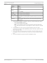
Page 62: ...ansformer If the Green LED is off then Turn off the Power Check the FX101 fuse for mains power to the Power Supply Box If O K then Check the FX102 fuse for 24 V power to the AutoDome Pendant If O K then If using a non Bosch power supply Check that the mains power to the power supply box is on If O K then Check that there is 24 V output from the transformer Check the connector on top of the AutoDom...

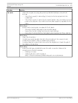
Page 63: ...ettings Ensure that On is selected from the Enable Audio drop down list Then click Set If O K then Check the microphone Connect appropriate speakers directly to the microphone at the camera site and confirm that the audio is clear and audible at the location An audio problem or noise at the source will further degrade as it travels through all the cables and connections If O K then Verify the cabl...

Page 64: ...the Gain settings and the peak gain value Access the Settings Web page for the IP enabled device Expand the Encoder Settings link then click Audio Settings Adjust the Gain level so that the peak value stays within the green area Refer to the VG5 AutoDome Installation Manual for complete information If O K then Check the location of the microphone and the audio cables Line level audio is typically ...

Page 65: ... the encoder via an Ethernet cable Figure 8 1 Typical Audio Connections for an Analog AutoDome 1 Microphone 6 Audio In 2 Coaxial Connection Microphone to Bosch Video Audio Encoder 10 m 33 ft maximum distance 7 Video In 3 VG5 600 Series AutoDome 8 Ethernet Connection Bosch Video Audio Encoder to a PC 4 Coaxial Connection VG5 600 Series Autodome to a Bosch Video Audio Encoder 9 Computer with Bosch D...

Page 66: ... 265 9 329 9 393 9 457 9 10 6 4 10 6 4 74 1 28 10 6 4 138 192 10 6 4 202 256 10 6 4 266 320 10 6 4 330 384 10 6 4 394 448 10 6 4 458 512 10 6 4 Table 9 1 Address Conversion Table for AD Manchester Systems Group 1 Group 2 Group 3 Group 4 Group 5 Group 6 Group 7 Group 8 IN OUT IN OUT IN OUT IN OUT IN OUT IN OUT IN OUT IN OUT 1 1 100 1 199 1 298 1 397 1 496 1 595 1 694 1 2 2 101 2 200 2 299 2 398 2 4...

Page 67: ......

Page 68: ...Bosch Security Systems Inc 850 Greenfield Road Lancaster PA 17601 USA www boschsecurity com Bosch Security Systems Inc 2014 Bosch Sicherheitssysteme GmbH Robert Bosch Ring 5 85630 Grasbrunn Germany ...

Reviews: