background image

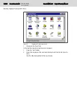
Fig.4-15:

"BTV 20" control panel icon

2.

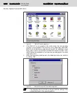
If the "BTV 20" is not available in the control panel, the corresponding

program is to be installed. The program is on the utility floppy disk SWD-

BTV20*-UTI-01VRS that is delivered with the BTV 20. Installation: Insert

floppy-disk in drive A: and enter the A:\SETUP command via Start - Run.

After finishing the installation, shut down the operating system and start

again with point 1.

3.

Select the desired keyboard layout in the following window and confirm it

by clicking "OK".

Fig.4-16:

Menu for the layout of the internal keyboard

The language that is set here must agree with the settings of the

external keyboard in the operating system.

36/135

Bosch Rexroth AG | Electric Drives

and Controls

Rexroth MTA 200 | Project Planning Manual

Machine Operator Terminal BTV 20.4A

Summary of Contents for Rexroth BTV 20.4A

Page 1: ...Electric Drives and Controls Pneumatics Service Linear Motion and Assembly Technologies Hydraulics ...

Page 2: ...erved in the event of the grant of a patent or the registration of a utility model or design DIN 34 1 The specified data is for product description purposes only and may not be deemed to be guaranteed unless expressly confirmed in the contract All rights are reserved with respect to the content of this documentation and the availa bility of the product Bosch Rexroth AG Bgm Dr Nebel Str 2 97816 Loh...

Page 3: ...w Voltage as Protection Against Electric Shock 17 3 3 3 Protection Against Dangerous Movements 18 3 3 4 Protection Against Magnetic and Electromagnetic Fields During Operation and Mounting 20 3 3 5 Protection Against Contact with Hot Parts 20 3 3 6 Protection During Handling and Mounting 21 3 3 7 Battery Safety 21 3 3 8 Protection Against Pressurized Systems 21 4 Machine Operator Terminal BTV 20 4...

Page 4: ...erial Interface COM1 45 VGA Screen Connection 45 Ethernet Interface 10 Base T 100 Base Tx 46 USB Interface 46 4 7 3 LPT1 Printer Interface and SIS 47 General Information 47 LPT1 interface 47 COM2 SIS interface 48 Configuration 48 4 7 4 Internal Wiring 48 4 7 5 Application Examples 50 Application Example for BTV 20 4A with INTERBUS Switch 50 Application Example with BTA 10 20 and BTC 06 Hand held T...

Page 5: ... 74 6 PC CPU Configuration 55 75 6 1 Brief Description 75 6 2 Technical Data Slot CPU Card Processor Specification 55 75 6 2 1 Electrical Specifications 75 6 2 2 CPU and Memory Specification 75 6 3 PhoenixBIOS Setup Processor Specification 55 76 6 3 1 General Information 76 6 3 2 Help Screen Online Help 76 6 3 3 Navigation in the PhoenixBIOS Setup 76 6 3 4 PhoenixBIOS Setup Main Menu 76 General In...

Page 6: ...iver 99 8 7 6 Status Indicators 99 SERCOS Ring H4 99 8 7 7 Connections 99 8 7 8 NCM in the BTV20 4A 100 8 8 Connecting Cables 100 8 8 1 General Information 100 8 8 2 Cable Specifications 100 8 9 NCIO Card 101 8 9 1 General Information 101 8 9 2 Slot Brackets 102 8 9 3 I O Interface X22 102 8 9 4 Installation 103 8 10 Phoenix Block I O Module ILB IB 24 DI16 DO16 104 8 10 1 General Information 104 8...

Page 7: ...ection 118 9 5 1 Brief Description 118 9 5 2 Setting of the I O Address 119 9 5 3 Technical Data 119 9 5 4 Interface Assignment 119 9 6 PROFIBUS DP Connection 121 9 6 1 Brief Description Master and Slave Connection 121 9 6 2 Setting I O addresses 122 9 6 3 Status and Diagnosis Information 122 9 6 4 Technical Data 123 9 6 5 Interface Assignment 123 9 7 Connecting the Hand held terminal BTC 06 124 9...

Page 8: ... 4 CMOS Variables 129 10 1 5 PLC Retain Data PLC Replacement 130 11 Service and Support 131 Index 133 VI VI Bosch Rexroth AG Electric Drives and Controls Rexroth MTA 200 Project Planning Manual Table of Contents ...

Page 9: ...ents is the basis of the MTA 200 control system The operating PC itself as well as the components that are already installed in the operator PC on delivery are described in detail in this documentation Fig 1 1 Control architecture The following components are included Type Description Chapter BTV 20 4A Operating PC with integrated control hardware chapter 4 Machine Operator Terminal BTV 20 4A on p...

Page 10: ...ufacturer must provide supplements to the hardware documen tation 1 3 Further Documentation Fig 1 2 System architecture The MTA 200 control system includes additional hardware components that are described in separate documents Type Description Documentation BTA 20 4 Machine operator control panel DOK SUPPL BTA20 4 PR0x EN P BTM 15 Machine operator panel DOK MTC200 BTM15 PR0x EN P BTM 16 Machine o...

Page 11: ...les Analog I O modules Counter module DOK CONTRL R IL INLINE KB0x EN P DOK CONTRL R IL IBSSYS AW0x EN P DOK CONTRL R IL PBSSYS AW0x EN P DOK CONTRL R IL IBS BK FK0x EN P DOK CONTRL R IL PB BK FK0x EN P DOK CONTRL R IL DIO FK0x EN P DOK CONTRL R IL AIO FK0x EN P DOK CONTRL R IL CNT AW0x EN P RECO Fieldline Interbus devices Profibus devices DOK CONTRL RF FLS IB PR0x EN P DOK CONTRL RF FLS PB PR0x EN...

Page 12: ...10 135 Bosch Rexroth AG Electric Drives and Controls Rexroth MTA 200 Project Planning Manual ...

Page 13: ...s must not be implemented or put into opera tion It must be ensured that the products are installed as specified in the doc umentation 2 1 2 Areas of Use and Application For BTV 20 4A Bosch Rexroth defines appropriate use for installation into a control panel into the wall or door of a control cabinet or directly into the en closure of a machine tool It may only be operated under the assembly and ...

Page 14: ...es on safety 2 3 ESD notes Electrostatically charged persons tools that are discharged via the controller or printed circuit boards can damage these components Therefore do observe the following notes CAUTION Risk of damage to the electronic components and deterioration of their operating safety by electrostatic charges Bodies coming into contact with components and printed circuit boards must be ...

Page 15: ...vable Thus a machine consists of the appropriate machine drive elements as well as con trol and power circuits which have been assembled for a specific application A machine is for example intended for processing treatment movement or packaging of a material The term machine also covers a combination of ma chines which are arranged and controlled in such a way that they function as a unified whole...

Page 16: ... and control system in order to eliminate the risk of injury and or property damage You must follow these safety instructions Bosch Rexroth is not liable for damages resulting from failure to observe the safety instructions Read the operating maintenance and safety instructions in your language before commissioning If you find that you cannot completely understand the application documentation in ...

Page 17: ...nal regulations The technical data connection and installation conditions of the compo nents are specified in the respective application documentations and must be followed at all times National regulations which the user must take into account European countries According to European EN standards United States of America USA National Electrical Code NEC National Electrical Manufacturers Associati...

Page 18: ...ution Minor or moderate injury or property damage may oc cur Fig 3 1 Hazard classification according to ANSI Z535 4 2002 3 3 Instructions with Regard to Specific Dangers 3 3 1 Protection Against Contact with Electrical Parts and Housings This section concerns components of the drive and control system with voltages of more than 50 volts Contact with parts conducting voltages above 50 volts can cau...

Page 19: ...en the component has been pow ered As a basic principle residual current operated circuit breakers cannot be used for electric drives to prevent direct contact Secure built in devices from penetrating foreign objects and water as well as from direct contact by providing an external housing for example a control cabinet WARNING High housing voltage and high leakage current Danger to life risk of in...

Page 20: ...ameters before commissioning Malfunction of sensors and encoders Defective components Software or firmware errors These errors can occur immediately after equipment is switched on or even after an unspecified time of trouble free operation The monitoring functions in the components of the drive and control system will normally be sufficient to avoid malfunction in the connected drives Regarding pe...

Page 21: ...y means of an emergency stop circuit or use a safe starting lockout Make sure that the drives are brought to a safe standstill before accessing or entering the danger zone Additionally secure vertical axes against falling or dropping after switching off the motor power by for example mechanically securing the vertical axes adding an external braking arrester clamping mechanism or ensuring sufficie...

Page 22: ...t Parts CAUTION Hot surfaces of components of the drive and control system Risk of burns Do not touch hot surfaces of for example braking resistors heat sinks supply units and drive controllers motors windings and laminated cores According to the operating conditions temperatures of the surfaces can be higher than 60 C 140 F during or after operation Before touching motors after having switched th...

Page 23: ...the batteries as this may cause leakage or explosion Do not throw batteries into open flames Do not dismantle batteries When replacing the battery batteries do not damage the electrical parts installed in the devices Only use the battery types specified for the product Environmental protection and disposal The batteries contained in the product are considered dangerous goods during land air and se...

Page 24: ...afety shoes safety gloves for example Immediately clean up any spilled liquids from the floor due to the risk of slipping Environmental protection and disposal The agents e g fluids used to operate the product might not be environmentally friendly Dispose of agents harmful to the environment separately from other waste Observe the national regulations of your country 22 135 Bosch Rexroth AG Electr...

Page 25: ...V 20 documentation DOK MTC200 BTV20 3 PR0x EN P The figure below shows the structure of the BTV 20 4 front panel Fig 4 1 BTV 20 4 front panel The front panel consists of a 4 mm thick aluminum panel with beveled edges It is coated with a chemical resistant polyester foil with embossed keys that covers the whole front panel The integrated 10 4 TFT color display provides excellent visualization of th...

Page 26: ... SERCOS interface NCZ module with one or two additional SERCOS interfaces PLC module with INTERBUS S or Profibus master connection NIO module for parallel connection of fast I Os All currently existing configurations can be found in the configuration type de sigantion code see chapter 4 8 2 Configuration Type Designation Code on page 57 All listed modules are described in detail in the following c...

Page 27: ...rior saving and the computer is rebooted CAUTION In the MTA 200 the reset button influences only the PC part of the control At first the NC part goes on running However when booting the PC part the com munication task to the NC will get stuck the BTV must be switched on and off again Therefore we recommend you not to use the reset button for the MTA Fig 4 3 Position of the reset button When using ...

Page 28: ...e BTV 20 is switched on and is supplied with voltage HDD lights as soon as the hard disk is accessed Fig 4 4 Operating displays 26 135 Bosch Rexroth AG Electric Drives and Controls Rexroth MTA 200 Project Planning Manual Machine Operator Terminal BTV 20 4A ...

Page 29: ...Shift The OP key row can also be individually labeled by slide in strips see chapter 4 2 6 Replacing the Slide in Strips on page 31 Explanation and Replication of Keys The BTV 20 keys can be replicated with a PC keyboard by the following short cuts Project Planning Manual Rexroth MTA 200 Electric Drives and Controls Bosch Rexroth AG 27 135 Machine Operator Terminal BTV 20 4A ...

Page 30: ...20 3 Corresponding key for the standard key board Fig 4 6 Shortcuts for BTV 20 keys 28 135 Bosch Rexroth AG Electric Drives and Controls Rexroth MTA 200 Project Planning Manual Machine Operator Terminal BTV 20 4A ...

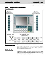
Page 31: ...eys are used for starting projected PLC or CNC movements PLC Function Keys Additionally the illuminated keys of the BTV 20 can be labeled with slide in strips Together with the key switches these keys are connected to the PLC these keys replace standard switching elements for fix PLC functions e g Basic setting or Stop after end of cycle etc Project Planning Manual Rexroth MTA 200 Electric Drives ...

Page 32: ...so address constants for Bosch Rexroth firmware data types can be used Machine function keys left right PLC program identifier Address constants Data type MFT_L A iMFK_L MFK_L MFT_R A iMFK_R MFK_R Fig 4 9 Addressing with address constants The MFK_L data type contains the L1 L2 L8 elements of the BOOL type The MFK_R data type contains the R1 R2 R8 elements of the BOOL type Example in the PLC progra...

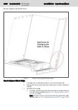
Page 33: ...n Strips General Information The 14 PLC function keys on the front of the BTV 20 can be labeled by using a slide in strip The key row above the PLC function keys OP2 OP9 is also freely configurable using slide in strips These strips which are already inserted when the device is delivered can be freely replaced Preprinted strips as well as a floppy disk with templates are also included in the scope...

Page 34: ...nsert the strip carefully To do this hold the strip at an acute angle to the front plate and thread it into the housing opening see fig 4 12 Replacing slide in strips on page 33 part A Note The slide in strip is to be inserted into the pocket of the glued front film see fig 4 12 Replacing slide in strips on page 33 If 32 135 Bosch Rexroth AG Electric Drives and Controls Rexroth MTA 200 Project Pla...

Page 35: ... to be taken into consideration The keyboard driver and thus the keyboard layout is already configured in the desired language under Windows corresponds the language of the installed operating system The connection of the external keyboard e g the PCK03 drawer keyboard is preset when the device is delivered as well Changes are to be made only if a keyboard is connected whose keyboard layout is dif...

Page 36: ...yout is displayed 1 Press the Add button 2 Select the language of the used external keyboard from the list input lo cale Use the default properties for this input locale 34 135 Bosch Rexroth AG Electric Drives and Controls Rexroth MTA 200 Project Planning Manual Machine Operator Terminal BTV 20 4A ...

Page 37: ...e changed keyboard is displayed in the window You cannot choose between the old and new key board layout as it is the case when the Add button is used For adapting the internal foil keyboard the additional BTV 20 icon is available in the Windows NT control panel Do the following steps 1 Call the BTV 20 entry in the Windows NT control panel Path Start Settings Control Panel BTV 20 Project Planning ...

Page 38: ...command via Start Run After finishing the installation shut down the operating system and start again with point 1 3 Select the desired keyboard layout in the following window and confirm it by clicking OK Fig 4 16 Menu for the layout of the internal keyboard The language that is set here must agree with the settings of the external keyboard in the operating system 36 135 Bosch Rexroth AG Electric...

Page 39: ...g Air pressure 860 to 1060 hPa 1500 m 12 000 m Max external magnetic field 6 x 10 4 Tesla 6 x 10 4 Tesla Max vibration 10 57 Hz Continuously 0 0375 mm amplitude occasionally 0 075 mm aplitude 57 150 Hz continuously 0 5 g constant acceleration occasion ally 1 0 g constant acceleration To be applied to each of the three vertically positioned axes according to standard IEC 60068 2 6 Max shock Occasio...

Page 40: ...ours After this time we recommend you to exchange these components as prevention 4 5 Dimensions 4 5 1 Housing Dimensions Fig 4 18 Dimensions front panel 38 135 Bosch Rexroth AG Electric Drives and Controls Rexroth MTA 200 Project Planning Manual Machine Operator Terminal BTV 20 4A ...

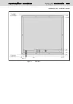
Page 41: ...Fig 4 19 Rear view Project Planning Manual Rexroth MTA 200 Electric Drives and Controls Bosch Rexroth AG 39 135 Machine Operator Terminal BTV 20 4A ...

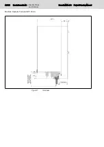
Page 42: ...Fig 4 20 Side view 40 135 Bosch Rexroth AG Electric Drives and Controls Rexroth MTA 200 Project Planning Manual Machine Operator Terminal BTV 20 4A ...

Page 43: ...Fig 4 21 Bottom view Project Planning Manual Rexroth MTA 200 Electric Drives and Controls Bosch Rexroth AG 41 135 Machine Operator Terminal BTV 20 4A ...

Page 44: ...4 6 Mounting Dimensions Fig 4 22 Mounting cut out 42 135 Bosch Rexroth AG Electric Drives and Controls Rexroth MTA 200 Project Planning Manual Machine Operator Terminal BTV 20 4A ...

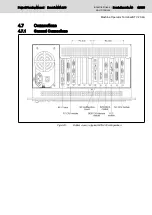
Page 45: ...ons 4 7 1 General Connections Fig 4 23 Bottom view in a typical MTA 200 configuration Project Planning Manual Rexroth MTA 200 Electric Drives and Controls Bosch Rexroth AG 43 135 Machine Operator Terminal BTV 20 4A ...

Page 46: ...Fig 4 24 Standard connections 44 135 Bosch Rexroth AG Electric Drives and Controls Rexroth MTA 200 Project Planning Manual Machine Operator Terminal BTV 20 4A ...

Page 47: ...in Designation Pin Designation 1 DCD 2 RxD 3 TxD 4 DTR 5 GND 6 DSR 7 RTS note1 8 CTS 9 RI Fig 4 27 Pin assignment of the COM1 serial interface The RS232 channel only works with 5 V voltage supply VGA Screen Connection Fig 4 28 VGA screen connection Project Planning Manual Rexroth MTA 200 Electric Drives and Controls Bosch Rexroth AG 45 135 Machine Operator Terminal BTV 20 4A ...

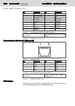
Page 48: ...thernet Interface 10 Base T 100 Base Tx Fig 4 31 Ethernet interface Pin Designation Pin Designation 1 TxD 2 TxD 3 RxD 4 N C 5 N C 6 RxD 7 N C 8 N C Fig 4 32 Pin assignment of the Ethernet interface Network card Intel R 82559ER PCI 10BASE T 100BASE Tx Fig 4 33 Network card in BTV 20 4 USB Interface Universal serial bus with USB Legacy Keyboard and USB floppy boot sup port Compatible with version 1 ...

Page 49: ...th interfaces are explained more detailed in the following LPT1 interface Fig 4 36 LPT1 interface PIN Signal designation PIN Signal designation 1 STB Strobe 2 PD0 3 PD1 4 PD2 5 PD3 6 PD4 7 PD5 8 PD6 9 PD7 10 ACK Acknowledge 11 Busy 12 PE Paper End 13 SLCT Select 14 AFD Auto Feed 15 ERR Error 16 INIT 17 SLCTIN Select In 18 GND 19 GND 20 GND 21 GND 22 GND 23 GND 24 GND 25 GND Fig 4 37 Pin assignment...

Page 50: ...indows desktop Fig 4 40 COM2 SIS interface configuration tool SISControl The COM2 SIS interface is internally performed via the COM4 port Therefore select under COM port always COM4 port that is shown as default here Then select the desired SIS mode 0 to 7 from the table corresponding to the used RS485 or RS422 interface The RS232 mode of the COM2 SIS interface is always active in dependent from t...

Page 51: ...ed and as well how to be connected to hard drive and floppy disk drive Fig 4 41 Inside of the BTV 20 4A Project Planning Manual Rexroth MTA 200 Electric Drives and Controls Bosch Rexroth AG 49 135 Machine Operator Terminal BTV 20 4A ...

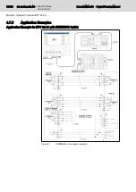
Page 52: ...es Application Example for BTV 20 4A with INTERBUS Switch Fig 4 42 INTERBUS S connection example 50 135 Bosch Rexroth AG Electric Drives and Controls Rexroth MTA 200 Project Planning Manual Machine Operator Terminal BTV 20 4A ...

Page 53: ...d PLC module via the IKB0015 cable Only RS422 communication can be established between the devi ces Further notes regarding the connection of the BTC 06 hand held terminal are in chapter 9 PLC Modules MTS P01 2 and MTS P02 2 on page 107 Project Planning Manual Rexroth MTA 200 Electric Drives and Controls Bosch Rexroth AG 51 135 Machine Operator Terminal BTV 20 4A ...

Page 54: ...onnection to MTS P0x 2 BTV 20 Fig 4 44 Connecting a BTA 10 20 to a BTV 20 52 135 Bosch Rexroth AG Electric Drives and Controls Rexroth MTA 200 Project Planning Manual Machine Operator Terminal BTV 20 4A ...

Page 55: ...d SERCOS Interface Fig 4 45 SERCOS connection BTV 20 4 A with a SERCOS interface module i e up to 8 axes Project Planning Manual Rexroth MTA 200 Electric Drives and Controls Bosch Rexroth AG 53 135 Machine Operator Terminal BTV 20 4A ...

Page 56: ...ows the pin assignment of the both connectors The table in chapter 4 8 3 Accessories on page 58 shows when which con nector housing for interface cables is used Fig 4 46 Pin assignment of the assembled connector housing The termination can be activated by a switch 54 135 Bosch Rexroth AG Electric Drives and Controls Rexroth MTA 200 Project Planning Manual Machine Operator Terminal BTV 20 4A ...

Page 57: ...Information 4 8 1 Type Designation Code Fig 4 47 Type designation code BTV 20 4 part 1 Project Planning Manual Rexroth MTA 200 Electric Drives and Controls Bosch Rexroth AG 55 135 Machine Operator Terminal BTV 20 4A ...

Page 58: ...Fig 4 48 Type designation code BTV 20 4 part 2 56 135 Bosch Rexroth AG Electric Drives and Controls Rexroth MTA 200 Project Planning Manual Machine Operator Terminal BTV 20 4A ...

Page 59: ...on Type Designation Code BTV 20 4A Fig 4 49 Configuration type designation code BTV 20 4A Project Planning Manual Rexroth MTA 200 Electric Drives and Controls Bosch Rexroth AG 57 135 Machine Operator Terminal BTV 20 4A ...

Page 60: ...m MN 278 143 15 m RS232 max 15 m Fig 4 50 IKB0005 IKB0012 000 0 MN 281 715 RS232 max 15 m Fig 4 51 IKB0012 000 0 IKS0106 000 0 MN 260 838 RS232 max 15 m configu ration Profibus Fig 4 52 IKS0106 000 0 IKS0190 MN 279 743 3 m MN 279 743 5 m MN 279 744 10 m MN 279 745 15 m RS422 max 15 m Fig 4 53 IKS0190 58 135 Bosch Rexroth AG Electric Drives and Controls Rexroth MTA 200 Project Planning Manual Machi...

Page 61: ...ax 15 m Fig 4 54 IKB0193 IKB0015 000 0 MN 282 870 RS422 max 400 m Fig 4 55 IKB0015 000 0 IKB0016 000 0 MN 282 871 RS422 max 400 m Fig 4 56 IKB0016 000 0 IKB0017 000 0 MN 282 872 RS485 max 400 m Fig 4 57 IKB0017 000 0 Project Planning Manual Rexroth MTA 200 Electric Drives and Controls Bosch Rexroth AG 59 135 Machine Operator Terminal BTV 20 4A ...

Page 62: ... m Fig 4 59 IKB0019 000 0 IKB0030 000 0 MN 291 736 configuration Interbus max 15 m Fig 4 60 IKB0030 000 0 IKB0031 000 0 MN 291 805 INTERBUS max 400 m IKB0031 000 5 MN 291 806 INTERBUS 0 5 m Fig 4 61 IKB0031 000 0 IKB0031 000 5 IKB0032 000 0 MN 291 807 INTERBUS max 400 m Fig 4 62 IKB0032 000 0 60 135 Bosch Rexroth AG Electric Drives and Controls Rexroth MTA 200 Project Planning Manual Machine Opera...

Page 63: ...00 0 IKB0034 000 0 MN 291 809 Profibus max 1000 m Fig 4 64 IKB0034 000 0 INS0619 K01 MN 279 583 Fig 4 65 INS0619 K01 Y connector for self assembly with termination INS0645 K01 MN 282 040 Fig 4 66 INS0645 K01 Y connector for self assembly with termination Project Planning Manual Rexroth MTA 200 Electric Drives and Controls Bosch Rexroth AG 61 135 Machine Operator Terminal BTV 20 4A ...

Page 64: ...41 K01 Profibus connector for self as sembly with termination mountable side by side Fig 4 69 Accessories MTS R Lockable floppy disk flap Furthermore a accessories kit can be ordered for the BTV 20 4 in order to backfit the device with a lockable floppy disk flap SUP M01 BTV20 Fig 4 70 SUP M01 BTV20 lockable floppy disk flap 62 135 Bosch Rexroth AG Electric Drives and Controls Rexroth MTA 200 Proj...

Page 65: ...el 365 x 4 x 0 8 mm Set of inscription plates Pre printed sample slide in strips Floppy disk with templates for independent creation of labels SWD BTV20 UTI 01VRS MS C1 44 Floppy disk with software for setting the keyboard language Slip case with software package Compilation of the ordered firmware and software Project Planning Manual Rexroth MTA 200 Electric Drives and Controls Bosch Rexroth AG 6...

Page 66: ...64 135 Bosch Rexroth AG Electric Drives and Controls Rexroth MTA 200 Project Planning Manual ...

Page 67: ...pecifications 5 2 2 CPU and Memory Specification Processor INTEL Mobile Pentium III min 700 MHz CPU Clock Rate Min 700 MHz System Clock Rate 100 MHz frontside bus Program memory 1 144 Pin SO DIMM 3 3 V PC100 max 256 MB Use 256 MB stacked SO DIMM modules only Do not use 256 MegaBit modules System Core INTEL 440BX AGP Set Fig 5 3 CPU and memory specification Project Planning Manual Rexroth MTA 200 E...

Page 68: ...ixBIOS Setup The following keys in the PhoenixBIOS Setup are of importance Keys Function F1 or Alt H Call General Help Esc Exit the menu or arrow keys Select different menus or arrow keys Select the desired menu item Tab or Shift Tab Jump to the next or to the previous menu item Home or End Move the cursor to the beginning or to the end of the cur rent menu PgUp or PgDn Move the cursor to the next...

Page 69: ... CPU only in its appearance it must be ensured that the PC CPU is not used as NC CPU and vice versa Otherwise the different BIOS settings of NC CPU and PCU CPU would prevent the BTV 20 4A from booting The BTV 20 4A with processor configuration 45 mandatorily re quires a MTA software version 23VRS or higher The BTV 20 4A cannot be operated with older versions 5 3 5 PhoenixBIOS Settings for the BTV ...

Page 70: ...ay depends on the IDE device 32 bit I O Enabled Transfer Mode Display depends on the IDE device Ultra DMA Mode Display depends on the IDE device Fig 5 7 IDE Device submenu Memory Shadow CC00 CFFF Disabled D000 D3FF Disabled D400 D7FF Disabled D800 DBFF Disabled DC00 DFFF Disabled Fig 5 8 Memory Shadow submenu Memory Cache Memory Cache Enabled Cache System BIOS area Write Protect Cache Video BIOS a...

Page 71: ...it I O Recovery 4 5 Fig 5 11 Advanced Chipset Control submenu PCI Configuration PCI IRQ line 1 Auto Select PCI IRQ line 2 Auto Select PCI IRQ line 3 Auto Select PCI IRQ line 4 Auto Select PCI PNP ISA UMB Region Exclusion Submenu PCI PNP ISA IRQ Resource Exclusion Submenu Default Primary Video Adapter AGP ISA graphics device installed No Assign IRQ to PCI VGA No Fig 5 12 PCI Configuration submenu P...

Page 72: ...evice Configuration Local Bus IDE adapter Both Onboard FDC Enabled Base I O address Primary External FDC Disabled Serial port A Enabled Base I O address 3F8 Interrupt IRQ4 Serial port B Enabled Mode Normal Base I O address 2F8 Interrupt IRQ3 Serial port C Enabled Base I O address 3E8 Interrupt IRQ11 Serial port D Enabled Base I O address 2E8 Interrupt IRQ11 Mode Normal External LPT Enabled Mode Bi...

Page 73: ...check reminder Disabled System backup reminder Disabled Fig 5 18 Security menu Power Power Savings Disabled Idle Mode Off Standby Timeout Off Auto Suspend Timeout Off Hard Disk Timeout Disabled Video Timeout Disabled Resume On Time Off Resume Time 00 00 00 Power Supply ATX Fig 5 19 Power menu Boot Floppy Check Disabled Summary Screen Disabled QuickBoot Mode Enabled Dark Boot Disabled Boot Device P...

Page 74: ...t the SO DIMM memory module at a 30 angle into the socket as shown in the figure below 2 Press the module carefully down until it locks in Fig 5 22 Installation of SO DIMM module illustration A Fig 5 23 Installation of SO DIMM module illustration B 72 135 Bosch Rexroth AG Electric Drives and Controls Rexroth MTA 200 Project Planning Manual PC CPU Configuration 45 ...

Page 75: ...ons 5 5 2 Connection for the Power Supply Cable To provide power to the IDE device an additional external voltage source is to be connected to the slot CPU card To do so use a standard power supply cable for 5 25 PC drives The pin assignment is as follows Fig 5 25 Connection for the power supply cable PIN Color Meaning 1 Yellow orange 12 V 2 Black GND 3 Black GND 4 Red 5 V Fig 5 26 Pin assignment ...

Page 76: ...evice connected is to be selected in the BIOS The Primary Master is set to Automatic detection and the Primary Slave is disabled in the delivery status The maximum allowed cable length for IDE cables is 50 cm Fig 5 27 Pin assignment 74 135 Bosch Rexroth AG Electric Drives and Controls Rexroth MTA 200 Project Planning Manual PC CPU Configuration 45 ...

Page 77: ...ectrical specifications 6 2 2 CPU and Memory Specification Processor Processor specification 55INTEL Celeron M ULV 373 1 0GHz CPU Clock Rate Processor specification 55 1 GHz System Clock Rate 333 MHz frontside bus Program memory 1 x 200 Pin SO DIMM max 1GB PC2700 DDR SDRAM DDR333 ECC pos sible with ECC SODIMM System Core INTEL 82855GME ICH4 Fig 6 3 CPU and memory specification Project Planning Man...

Page 78: ... the PhoenixBIOS Setup The following keys in the PhoenixBIOS Setup are of importance Keys Function F1 or Alt H Call General Help Esc Exit the menu or arrrow keys Select different menus or arrow keys Select the desired menu item Tab or Shift Tab Jump to the next or previous menu item Home or End Move the cursor to the beginning or to the end of the current menu PgUp or PgDn Move the cursor to the n...

Page 79: ...only in its appearance it must be ensured that the PC CPU is not used as NC CPU and vice versa Otherwise the different BIOS settings of NC CPU and PCU CPU would prevent the BTV 20 4A from booting The BTV 20 4A with processor configuration 45 mandatorily re quires a MTA software version 23VRS or higher The BTV 20 4A cannot be operated with older versions 6 3 5 PhoenixBIOS Settings BTV20 3 Processor...

Page 80: ...play depends on the IDE device Ultra DMA Mode Display depends on the IDE device Fig 6 7 IDE Device submenu Keyboard Features NumLock On Key Click Disabled Keyboard auto repeat rate 30 sec Keyboard auto repeat delay sec Fig 6 8 Keyboard Features submenu Boot Options Boot time Diagnostic Screen Enabled QuickBoot Mode Enabled Summary screen Disabled Boot with keyboard Disabled Floppy check Disabled H...

Page 81: ...IRQ10 Serial Port D Enabled Mode Normal Base I O address 2E8 Interrupt IRQ11 External Parallel Port Enabled Base I O address 378 Interrupt IRQ7 Mode Bi Directional Floppy disk controller Enabled External Diskette Controller Disabled Watchdog timeout Disabled Fig 6 11 I O Device Configuration submenu Advanced Chipset Control Legacy USB Support Enabled USB support Enabled USB 2 0 functionality Disab...

Page 82: ...ub Menu Cache Memory Memory Cache Enabled Cache System BIOS area Write Protect Cache Video BIOS area Write Protect Cache Extended Memoy Area Write Back Cache D000 D3FF Disabled Cache D400 D7FF Disabled Cache D800 DBFF Disabled Cache DC00 DFFF Disabled Fig 6 15 Cache Memory submenu PCI Configuration PCI PNP ISA UMB Region Exclusion Submenu PCI PNP ISA IRQ Resource Exclusion Submenu PCI IRQ line 1 A...

Page 83: ...No password Enter Fig 6 19 Security menu Power After Power Failure Power ON CPU Control Sub Menu Submenu Hardware Monitor Submenu Temperature Management Submenu Fig 6 20 Power menu CPU Control Sub Menu CPU Sleep Disabled Cx States Disabled Speed Step Technology Disabled Thermal Control Circuit TM1 Fig 6 21 CPU Control Sub Menu Hardware Monitor Vcore CPU Display of the current value V 2 5 Display o...

Page 84: ...Alarm Temperature 80 C CPU Alarm Hysteresis 5 C Throttling Status Display of the current value Fig 6 23 Temperature Management submenu Boot Boot priority order 1 IDE 0 2 Legacy Floppy Drives 3 4 5 6 7 8 Excluded from boot order IDE 1 IDE 2 IDE 3 USB FDC USB HDD USB CDROM USB KEY USB ZIP USB LS120 PCI LAN PCI SCSI Fig 6 24 Boot menu 82 135 Bosch Rexroth AG Electric Drives and Controls Rexroth MTA 2...

Page 85: ... FD serial interface and Ethernet are not used and are disabled via BIOS 7 2 Technical Data 7 2 1 Electrical Specifications Voltage supply 5 12 V 3 Power consumption 10 20 W typically depending on the processor type Battery 3 6 volt lithium battery size AA Fig 7 2 Electrical specifications 7 2 2 CPU and Memory Specification Processor INTEL Mobile Pentium III min 400 MHz CPU Clock Rate Min 400 MHz ...

Page 86: ...oard have to be directly connected to the NC CPU The start and the condition of the BIOS editor are described in chapter 3 7 3 2 PhoenixBIOS settings of the NC CPU Main System Time Current time System Date Current date Legacy Diskette A 1 44 1 25 MB 3 Legacy Diskette B disabled Primary Master none Primary Slave none Secondary Master none Secondary Slave none Memory Shadow Submenu Memory Cache Subm...

Page 87: ...tures Submenu I O Device Configuration Submenu Large Disk Access Mode DOS SMART Device Monitoring Enabled Halt On Errors No Fig 7 7 Advanced menu Advanced Chipset Control Graphics Aperture 64 Mb Enabled memory gap Disabled ECC Config Disabled SERR signal condition Multiple bit 8 bit I O Recovery 4 5 16 bit I O Recovery 4 5 Fig 7 8 Advanced Chipset Control submenu PCI Configuration PCI IRQ line 1 9...

Page 88: ...lable IRQ9 Available IRQ10 Available IRQ11 Available IRQ12 Available Fig 7 11 PCI PNP ISA IRQ Resource Exclusion submenu Keyboard Features NumLock Auto Key Click Disabled Keyboard auto repeat rate 30 sec Keyboard auto repeat delay sec Fig 7 12 Keyboard Features submenu I O Device Configuration Local Bus IDE adapter Disabled Onboard FDC Enabled Primary External FDC Disabled Serial port A Disabled S...

Page 89: ... check reminder Disabled System backup reminder Disabled Fig 7 15 Security menu Power Power Savings Disabled Idle Mode Off Standby Timeout Off Auto Suspend Timeout Off Hard Disk Timeout Disabled Video Timeout Disabled Resume On Time Off Resume Time 00 00 00 Power Supply AT Fig 7 16 Power menu Boot Floppy Check Disabled Summary Screen Disabled QuickBoot Mode Enabled Dark Boot Disabled Boot Device P...

Page 90: ...iority Removable Devices Hard Drive CD ROM drive Network Boot Fig 7 18 Boot Device Priority submenu 88 135 Bosch Rexroth AG Electric Drives and Controls Rexroth MTA 200 Project Planning Manual PC CPU Configuration 44 ...

Page 91: ...tion card 8 2 Features PCI Interface Flash memory with up to 1024 kB 4 SERCOS interfaces with 2 4 8 16 MBaud Bus master ability for cyclic data transmission between SERCON components and the RAM 32 bit RISC communication processor clocked with 40 MHz 128 kB flash EPROM 10 kB RAM and 2 kB dual port RAM to the PCI bus 3 processor internal serial interfaces 8 3 Available Versions The NC multifunction...

Page 92: ...Fig 8 2 Numerical code of the NCM card 90 135 Bosch Rexroth AG Electric Drives and Controls Rexroth MTA 200 Project Planning Manual NC Multifunction Card NCM02 ...

Page 93: ...8 4 Interfaces Fig 8 3 Interfaces of the NC multifunction card Project Planning Manual Rexroth MTA 200 Electric Drives and Controls Bosch Rexroth AG 91 135 NC Multifunction Card NCM02 ...

Page 94: ...The MTA 200 does not provide the handwheel interfaces and the 4 SERCOS ring 92 135 Bosch Rexroth AG Electric Drives and Controls Rexroth MTA 200 Project Planning Manual NC Multifunction Card NCM02 ...

Page 95: ...ng and Component Diagrams 8 5 1 NCM0201 Fig 8 4 NC multifunction card with 1 SERCOS ring Project Planning Manual Rexroth MTA 200 Electric Drives and Controls Bosch Rexroth AG 93 135 NC Multifunction Card NCM02 ...

Page 96: ...8 5 2 NCM0202 Fig 8 5 NC multifunction card with 2 SERCOS rings 94 135 Bosch Rexroth AG Electric Drives and Controls Rexroth MTA 200 Project Planning Manual NC Multifunction Card NCM02 ...

Page 97: ...8 5 3 NCM0204 Fig 8 6 NC multifunction card with 4 SERCOS rings Project Planning Manual Rexroth MTA 200 Electric Drives and Controls Bosch Rexroth AG 95 135 NC Multifunction Card NCM02 ...

Page 98: ... connected to the CNC bypassing the PLC A total of 16 inputs and 16 outputs is provided The interface is designed as a standard Interbus S interface The signals are to be connected via an Interbus S I O module This can be done in 2 ways Internal implementation via NCIO card This option provides a solution with a 37 pin Sub D connector that is compatible with the earlier BTVs see chapter 8 9 NCIO C...

Page 99: ...ED Description green Ready for operation yellow red Error Fig 8 10 Status indicators for fast I Os H6 8 7 Additional SERCOS Rings 8 7 1 General Information On the NC multifunction card one pair of fibre optics cable is available for the first SERCOS ring The interface adapters NCMZ003 for one additional SERCOS ring and NCMZ004 for two additional SERCOS rings are available for connecting further SE...

Page 100: ...SERCOS ring 8 7 3 NCMZ004 Fig 8 12 Slot bracket for two additional SERCOS rings 8 7 4 X24 Transmitter X24 2 transmitter TX 2 SERCOS ring 98 135 Bosch Rexroth AG Electric Drives and Controls Rexroth MTA 200 Project Planning Manual NC Multifunction Card NCM02 ...

Page 101: ...RCOS Ring H4 LED Description green Data is received yellow Data is transmitted red Distortion or line break Fig 8 13 Status indicator for SERCOS ring H4 8 7 7 Connections Fig 8 14 Connection of additional SERCOS rings to NCM Project Planning Manual Rexroth MTA 200 Electric Drives and Controls Bosch Rexroth AG 99 135 NC Multifunction Card NCM02 ...

Page 102: ...via the SERCOS fiber optics cables The connection is designed as a ring i e at least two SERCOS fiber optics cables are used depending on the number of drives Depending on the loacation of use two different cables are used For wiring within the control cabinet a fiber optic cable with a diameter of 2 2 mm is used Outside of the control cabinet a sheathed fiber optic cable with a diameter of 6 0 mm...

Page 103: ...and 16 digital outputs are applied The assignment and designation of the signals corresponds exactly to the assignment of the MIO card of the previous controls The connection between NCIO card and NCM is established via the IKS0031 connecting cable which is included in the BTV20 4A standard delivery if the NCIO option 2V in the type designation code is contained Fig 8 17 NCIO Card CAUTION Danger o...

Page 104: ...or port 23 bit 0 Uexternal 2 Port 23 bit 0 encoder 24V Input 1 3 Port 23 bit 1 Input 4 Port 23 bit 2 Input 5 Port 23 bit 3 Input 6 Port 23 bit 4 Input 7 Port 23 bit 5 Input 8 Port 23 bit 6 Input 9 Port 23 bit 7 Input 10 Input 24V for output signals Uexternal 11 GND for output signals Uexternal 12 not assigned Output 102 135 Bosch Rexroth AG Electric Drives and Controls Rexroth MTA 200 Project Plan...

Page 105: ...signed Output 37 not assigned Output Input addressable via analog C commands see LINPOS 1 Active signal level High 1 0 Active signal level Low 0 CAUTION The EMERGENCY STOP contacts must always be laid out as NC contacts so that they immediately stop all movements if a break occurs in the connecting cables Signal level 24 V DC 10 Max Load per output 80 mA Input current approx 5 mA 8 9 4 Installatio...

Page 106: ...ecting the Phoenix block module the IKB0032 Rexroth cable can be used The 9 pin D Sub connector is connected to the NCM card connector X23 The other end of the cable has free core ends which must be connected at connector 1 of the module as follows 104 135 Bosch Rexroth AG Electric Drives and Controls Rexroth MTA 200 Project Planning Manual NC Multifunction Card NCM02 ...

Page 107: ...essing enable 9 1 1 3 Set up mode 10 1 4 not assigned 11 1 5 not assigned 12 1 6 not assigned 13 1 7 Feed enable all axes 14 1 1 8 E STOP 15 0 1 9 Port 23 bit 0 encoder 0 1 1 10 Port 23 bit 1 1 1 11 Port 23 bit 2 2 1 12 Port 23 bit 3 3 1 13 Port 23 bit 4 4 1 14 Port 23 bit 5 5 1 15 Port 23 bit 6 6 1 16 Port 23 bit 7 7 Fig 8 22 Signal assignment of the inputs Outputs Terminal Signal designation IBS...

Page 108: ...not assigned 3 2 13 not assigned 4 2 14 not assigned 5 2 15 not assigned 6 2 16 not assigned 7 Input addressable via analog C commands see LINPOS 1 Active signal level High 1 0 Active signal level Low 0 Fig 8 23 Output signal assignment 106 135 Bosch Rexroth AG Electric Drives and Controls Rexroth MTA 200 Project Planning Manual NC Multifunction Card NCM02 ...

Page 109: ... P01 2 and MTS P02 2 provide a BT bus operating ter minal bus which can be used to operate up to 4 operator terminals BTM 15 16 BTA 20 etc Cable lengths up to 50 m are possible between the connection and the last user The MTS P0 2 is provided with 16 TTL inputs and 16 TTL outputs They can be used to for instance directly connect the machine function keys and key switches of the BTV20 The MTS P mod...

Page 110: ...Fig 9 1 MTS P01 2 Fig 9 2 MTS P02 2 108 135 Bosch Rexroth AG Electric Drives and Controls Rexroth MTA 200 Project Planning Manual PLC Modules MTS P01 2 and MTS P02 2 ...

Page 111: ...rage temperature 20 C to 70 C Dimensions WxHxD 22 mm x 145 mmm x 295 mm Weight approx 0 3 kg 9 2 2 Supply Voltage Nominal value 5 V 12 V 12 V Permissible ripple 50 mV 120 mV 120 mV Permissible voltage range 4 875 11 4 V 12 6 V 12 6 V 11 4 V Max current consumption 5V MTS P01 2 MTS P02 2 0 6 A supply voltage for PC 104 modules up to max 2 5A 1 8 A supply voltage for PC 104 modules up to max 2 5A Pr...

Page 112: ...for Machine Function Keys X8 If the MTS P0 2 is used in Bosch Rexroth industrial PCs of type BTV 20 30 the machine function keys are directly wired onto the PLC module X8 To use the machine function keys select the M keys activation via the I O configurator of WinPCL see DOK CONTRL WINPCL 6VRS AW01 EN P The left key row is assigned to the less significant input byte and the right key row is assign...

Page 113: ...put correspondingly For more detailed information please refer to the PLC programming instructions DOK CONTRL WINPCL 6VRS AW01 EN P 9 3 7 BT BUS X15 General Information The BT bus can be used for connecting up to four operator panels of type BTM 15 16 or BTA 20 The maximum length of the BT bus may be up to 50m from the connection point to the last user This applies to the connection of only one de...

Page 114: ... assigned its own address Each of the two image memories has a size of 128 bytes which are available for the connected operating devices The number of bytes assigned in the memory depends on the operator panel see fig 9 6 Memory requirements of the operating devices on page 113 112 135 Bosch Rexroth AG Electric Drives and Controls Rexroth MTA 200 Project Planning Manual PLC Modules MTS P01 2 and M...

Page 115: ...re assigned in the input and output image memory without any gaps according to the storage requirements of the operating devi ces The example fig 9 7 Memory assignment in BT bus on page 113 illustrates the principle of the memory assignment of the BT bus Fig 9 7 Memory assignment in BT bus 9 4 Commissioning 9 4 1 Installation Plug the MTS P module into an unoccupied ISA bus slot of your industrial...

Page 116: ... switch described in fig 9 8 Position of addressing switch on page 114 depending on the type of control master slave Fig 9 8 Position of addressing switch MTS P0 2 1 2 3 4 5 6 7 8 I O address hex MTA200 OFF OFF OFF OFF OFF OFF OFF OFF 31C Fig 9 9 DIP switch configuration of MTS P0 2 modules 9 4 3 Battery If an MTS assembly is not operated or is stored for more than 6 months user specific PLC data ...

Page 117: ... any other one digit code followed by a period is displayed cus tomer service must be immediately notified Error Display Error states are indicated by three digit error codes on the successively flashing 7 segment display The error codes represented correspond to the system error messages of the user interface BOF GBO Code Meaning 007 Software version error 008 Self test was not successful 052 PLC...

Page 118: ... modem 15 NC Fig 9 13 Pin assignment COM interface X16 PIN Signal designation PIN Signal designation 1 Data Out 2 Data In 2 GND 4 NC 5 5V 6 Data Out 7 Data In 8 NC 9 Detection of the assignment Fig 9 14 Pin assignment BT bus X15 PIN Function X1 1 X1 4 Supply voltage VCC X1 5 X1 20 Input 0 15 X1 21 X1 36 Output 0 15 X1 37 X1 40 GND Fig 9 15 Pin assignment I O connector 40 pin X12 PIN Signal designa...

Page 119: ...nation 13 S10 14 S11 15 S12 16 S13 17 S14 18 S15 19 GND 20 GND Fig 9 16 Pin assignment machine function keys X8 Project Planning Manual Rexroth MTA 200 Electric Drives and Controls Bosch Rexroth AG 117 135 PLC Modules MTS P01 2 and MTS P02 2 ...

Page 120: ... IBM2 printed circuit board is a INTERBUS master connection of the 4th generation in PC 104 format It can be used for the connection of simple sen 118 135 Bosch Rexroth AG Electric Drives and Controls Rexroth MTA 200 Project Planning Manual PLC Modules MTS P01 2 and MTS P02 2 ...

Page 121: ...programming interface see DOK CONTRL WINPCL 6VRS AW 9 5 2 Setting of the I O Address DIP switch S1 must be set as follows default setting so that PCB IBM2 can be addressed via the PC 104 bus 1 2 3 4 5 6 7 8 Address OFF OFF ON OFF OFF ON OFF OFF 120h Fig 9 18 Setting S1 DIP switch 9 5 3 Technical Data Power supply Operating voltage 5VDC 5 400 mA Interface data Communication interface 2 wire remote ...

Page 122: ...RBUS diagnosis interface X64 RS232 C Pin Signal designation Pin Signal designation 1 DO 2 DI 3 COM 4 GND 5 5V 6 DO 7 DI 8 Vcc 9 RBST Fig 9 20 Pin assignment INTERBUS interface X60 remote bus 120 135 Bosch Rexroth AG Electric Drives and Controls Rexroth MTA 200 Project Planning Manual PLC Modules MTS P01 2 and MTS P02 2 ...

Page 123: ...it boards DPM01 master and DPS01 slave are intelligent PROFIBUS DP connections in PC 104 format They are used to process the protocols of the data transmission between the PLC and the decentralized Project Planning Manual Rexroth MTA 200 Electric Drives and Controls Bosch Rexroth AG 121 135 PLC Modules MTS P01 2 and MTS P02 2 ...

Page 124: ... The line length is reduced to max 200 m if the transmission rate is 1 5 MBaud and to 100 m if the trans mission rate is 12 MBaud Slaves with inputs of a maximum of 244 bytes and outputs of a maximum of 244 bytes can be connected to the LK DPM01 master The total of inputs and outputs of all slaves must not exceed 512 bytes each The LK DPS01 slave must be configured in such a way that the total of ...

Page 125: ...ED yellow Status On Data exchange with slaves active master Data exchange with master active slave Off No data exchange Fig 9 23 Status and diagnosis displays 9 6 4 Technical Data Power supply Operating voltage 5VDC 5 650 mA Interface data Communication interface PROFIBUS DP max 12 MBaud potential free Diagnosis interface RS 232C 9600 Baud Operating conditions Operating temperature 0 C 55 C Storag...

Page 126: ...cting the Hand held terminal BTC 06 The hand held terminal BTC 06 may only and exclusively be connected via the machine operator panels BTA 10 or BTA 20 RS232 operation is converted into RS422 operation by the interface converter integrated in the BTA 10 20 see fig 9 27 MTS P with BTC 06 via RS232 interface on page 125 RS422 op eration with BTC 06 also is only possible via BTA 10 20 However no int...

Page 127: ...Fig 9 27 MTS P with BTC 06 via RS232 interface Project Planning Manual Rexroth MTA 200 Electric Drives and Controls Bosch Rexroth AG 125 135 PLC Modules MTS P01 2 and MTS P02 2 ...

Page 128: ...Fig 9 28 MTS P with BTC 06 via RS422 interface 126 135 Bosch Rexroth AG Electric Drives and Controls Rexroth MTA 200 Project Planning Manual PLC Modules MTS P01 2 and MTS P02 2 ...

Page 129: ...8 1 MTS P0 2 D2 B1 NN NN NN FW Fig 9 29 Structure of MTS P0 2 D2 B1 NN NN NN FW configuration Project Planning Manual Rexroth MTA 200 Electric Drives and Controls Bosch Rexroth AG 127 135 PLC Modules MTS P01 2 and MTS P02 2 ...

Page 130: ... 2 D2 P1 NN NN NN FW Fig 9 30 Structure of MTS P0 2 D2 P1 NN NN NN FW configuration 128 135 Bosch Rexroth AG Electric Drives and Controls Rexroth MTA 200 Project Planning Manual PLC Modules MTS P01 2 and MTS P02 2 ...

Page 131: ... Control Parameters NCM Replacement Parameters are handled by the Project Navigator of the MTA user interface This ensures that a copy of the current parameters of the NCM card is always stored on the hard disk After the BTV or NCM has been replaced the last valid parameter set is to be newly loaded into the the NCM using the Download function Before use the NCM card must be initialized in the BTV...

Page 132: ...t Remanent variables are stored on the PLC card if they are used in the PLC project These variables are deleted if the PLC card is replaced firmware is downloaded or a new project is loaded The retain data can be stored directly in the PLC programming Under WinPCL the retain data is saved under Start Variable Values 130 135 Bosch Rexroth AG Electric Drives and Controls Rexroth MTA 200 Project Plan...

Page 133: ...0 60 49 0 171 333 88 26 or 49 0 172 660 04 06 Fax 49 0 9352 40 49 41 e mail service svc boschrexroth de Internet http www boschrexroth com You will also find additional notes regarding service maintenance e g delivery addresses and training 1 Central European Time CET For quick and efficient help please have the following information ready detailed description of the fault and the circumstances in...

Page 134: ...132 135 Bosch Rexroth AG Electric Drives and Controls Rexroth MTA 200 Project Planning Manual ...

Page 135: ...og 111 Heat loss 37 Housing opening 32 I I O interface X22 102 Image memory 112 Inappropriate use 12 Consequences exclusion of liability 11 Input locale 34 INTERBUS loop 119 INTERBUS master connection 107 118 Interface assignment 116 123 Internal foil keyboard 35 K Keyboard 37 Keyboard driver 33 Keyboard language 33 Keyboard layout 33 Key labeling 31 Key switch 110 Key switches 107 L LPT1 47 M Mac...

Page 136: ...19 Repeater 122 Reset button 25 S Safety instructions for electric drives and con trols 13 Scope of delivery 63 SERCOS interface module 53 S Service Hotline 131 Service interface 25 Shortcuts 27 Signal level 103 Slide in strip 31 Slide in strips 29 Slide in strips replacing 32 Slots 37 Stand Alone PLC 24 Support see Service Hotline 131 T Technical data 37 NC CPU 83 Slot CPU card 65 75 U Use 11 V V...

Page 137: ...Notes Project Planning Manual Rexroth MTA 200 Electric Drives and Controls Bosch Rexroth AG 135 135 ...

Page 138: ... DOK MTA200 BTV20 4A PR02 EN P R911307076 Bosch Rexroth AG Electric Drives and Controls P O Box 13 57 97803 Lohr Germany Bgm Dr Nebel Str 2 97816 Lohr Germany Tel 49 0 93 52 40 0 Fax 49 0 93 52 48 85 www boschrexroth com ...

Reviews: