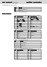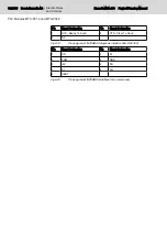
Terminal Point
Assignment
Remark
Cable color
1.1
Receiving
Green
2.1
DO1
Receiving
Yellow orange
1.2
Transmitting
Pink
2.2
DI1
Transmitting
Gray
1.3
GND
Reference potential Brown
Not assigned
White
1.4, 2.4
Shield
Shielding
Shielding braid
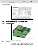
Fig.8-21:
IKB0032 pin assignment
8.10.3
Signal Assignment
If this I/O assembly is used, the following signal assignment is applicable:
Inputs:
Terminal
Signal designation
IBS data bit
Note
1.1
Read enable
8
1
1.2
Processing enable
9
1
1.3
Set-up mode
10
1.4
not assigned
11
1.5
not assigned
12
1.6
not assigned
13
1.7
Feed enable all axes
14
1
1.8
E-STOP
15
0
1.9
Port 23, bit 0,
0
1,*
1.10
Port 23, bit 1
1
*
1.11
Port 23, bit 2
2
*
1.12
Port 23, bit 3
3
*
1.13
Port 23, bit 4
4
*
1.14
Port 23, bit 5
5
*
1.15
Port 23, bit 6
6
*
1.16
Port 23, bit 7
7
*
Fig.8-22:
Signal assignment of the inputs
Outputs:
Terminal
Signal designation
IBS data bit
Note
2.1
not assigned
8
2.2
not assigned
9
2.3
not assigned
10
2.4
not assigned
11
2.5
not assigned
12
2.6
not assigned
13
Project Planning Manual | Rexroth MTA 200
Electric Drives
and Controls
| Bosch Rexroth AG 105/135
NC Multifunction Card NCM02
Summary of Contents for Rexroth BTV 20.4A
Page 12: ...10 135 Bosch Rexroth AG Electric Drives and Controls Rexroth MTA 200 Project Planning Manual ...
Page 66: ...64 135 Bosch Rexroth AG Electric Drives and Controls Rexroth MTA 200 Project Planning Manual ...
Page 134: ...132 135 Bosch Rexroth AG Electric Drives and Controls Rexroth MTA 200 Project Planning Manual ...


