5.5
Temporary Connection of Further IDE Devices
5.5.1
General Information
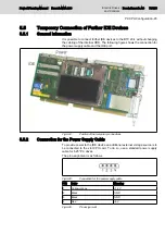
It is possible to connect further IDE devices to the BTV 20.4 without changing
the cabling of the internal HDD. The following figure shows the connection for
the power supply cable and the IDE port:
Fig.5-24:
Position of the temporary connections
5.5.2
Connection for the Power Supply Cable
To provide power to the IDE device an additional external voltage source is to
be connected to the slot CPU card. To do so, use a standard power supply
cable for 5.25" PC drives.
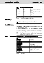
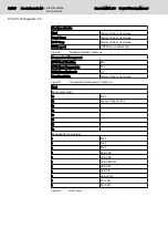
The pin assignment is as follows:
Fig.5-25:
Connection for the power supply cable
PIN
Color
Meaning
1
Yellow orange
+12 V
2
Black
GND
3
Black
GND
4
Red
+5 V
Fig.5-26:
Pin assignment
Project Planning Manual | Rexroth MTA 200
Electric Drives
and Controls
| Bosch Rexroth AG
73/135
PC CPU Configuration -45
Summary of Contents for Rexroth BTV 20.4A
Page 12: ...10 135 Bosch Rexroth AG Electric Drives and Controls Rexroth MTA 200 Project Planning Manual ...
Page 66: ...64 135 Bosch Rexroth AG Electric Drives and Controls Rexroth MTA 200 Project Planning Manual ...
Page 134: ...132 135 Bosch Rexroth AG Electric Drives and Controls Rexroth MTA 200 Project Planning Manual ...


