background image

  | 

3

Bosch Power Tools

2 609 006 763 | (17.1.13)

D

C

B

A

1

20

1

20

OBJ_BUCH-1824-001.book  Page 3  Thursday, January 17, 2013  10:33 AM

Summary of Contents for PWS

Page 1: ...7500 7800 850 115 850 125 de Originalbetriebsanleitung en Original instructions fr Notice originale es Manual original pt Manual original it Istruzioni originali nl Oorspronkelijke gebruiks aanwijzing da Original brugsanvisning sv Bruksanvisning i original no Original driftsinstruks fi Alkuperäiset ohjeet el Πρωτότυπο οδηγιών χρήσης tr Orijinal işletme talimatı OBJ_DOKU 32634 001 fm Page 1 Thursda...

Page 2: ...sh Page 16 Français Page 26 Español Página 37 Português Página 48 Italiano Pagina 58 Nederlands Pagina 69 Dansk Side 80 Svenska Sida 89 Norsk Side 98 Suomi Sivu 107 Ελληνικά Σελίδα 116 Türkçe Sayfa 127 OBJ_BUCH 1824 001 book Page 2 Thursday January 17 2013 10 33 AM ...

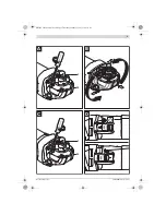
Page 3: ... 3 Bosch Power Tools 2 609 006 763 17 1 13 D C B A 1 20 1 20 OBJ_BUCH 1824 001 book Page 3 Thursday January 17 2013 10 33 AM ...

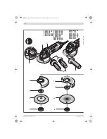
Page 4: ...00 115 PWS 730 115 PWS 75 115 PWS 700 PWS 750 125 PWS 780 125 PWS 7500 PWS 7800 PWS 850 115 PWS 850 125 PWS 7000 PWS 700 125 PWS 720 115 PWS 700 115 PWS 7 115 PWS 680 115 8 11 9 7 6 10 7 9 2 1 3 3 4 OBJ_BUCH 1824 001 book Page 4 Thursday January 17 2013 10 33 AM ...

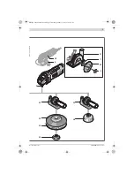
Page 5: ... 5 Bosch Power Tools 2 609 006 763 17 1 13 5 19 4 9 18 7 17 13 14 15 12 16 12 OBJ_BUCH 1824 001 book Page 5 Thursday January 17 2013 10 33 AM ...

Page 6: ...mweltgerechten Wiederverwertung zugeführt werden Werfen Sie Elektrowerkzeuge nicht in den Hausmüll Nur für EU Länder Gemäß der Europäischen Richtlinie 2002 96 EG über Elektro und Elektronik AltgeräteundihrerUmsetzunginnationales Recht müssen nicht mehr gebrauchsfähige Elektrowerkzeuge getrennt gesammelt und einer umweltgerechten Wiederverwertung zugeführt werden Änderungen vorbehalten English Safe...

Page 7: ...gnment or bind ing of moving parts breakage of parts and any other conditionthat may affectthe power tool s operation If damaged have the power tool repaired before use Many accidents are caused by poorly maintained power tools Keepcuttingtoolssharpandclean Properly maintained cuttingtoolswithsharpcuttingedgesarelesslikelytobind and are easier to control Use the power tool accessories and tool bit...

Page 8: ...ese condi tions Kickback is the result of power tool misuse and or incor rect operating procedures or conditions and can be avoid ed by taking proper precautions as given below Maintainafirmgriponthepowertoolandpositionyour body and arm to allow you to resist kickback forces Al ways use auxiliary handle if provided for maximum control over kickback or torque reaction during start up The operator c...

Page 9: ...s are hiddenintheworkareaorcallthelocalutilitycompany for assistance Contact with electric lines can lead to fire and electric shock Damaging a gas line can lead to explo sion Penetrating a water line causes property damage or may cause an electric shock Release the On Off switch and set it to the off position whenthepower supply is interrupted e g incase ofa powerfailure orwhenthe mains plug is p...

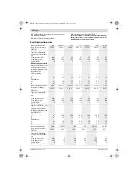
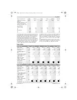
Page 10: ...s2 8 0 1 5 5 5 1 5 8 0 1 5 5 5 1 5 8 0 1 5 5 5 1 5 8 0 1 5 5 5 1 5 8 0 1 5 5 5 1 5 8 0 1 5 5 5 1 5 Measured sound values de termined according to EN 60745 PWS 700 115 720 115 730 115 750 115 750 125 75 115 3 603 CA2 4 CA2 4 CA2 4 CA2 4 CA2 4 CA2 4 Typically the A weighted noise levels of the product are Sound pressure level Sound power level Uncertainty K Wear hearing protection dB A dB A dB 93 10...

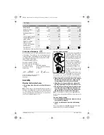
Page 11: ... 0 1 5 10 0 1 5 5 0 1 5 10 0 1 5 5 0 1 5 10 0 1 5 5 0 1 5 10 0 1 5 5 0 1 5 Angle Grinder PWS 680 115 700 7 115 700 115 7000 700 125 Article number 3 603 CA2 0 CA2 0 CA2 0 CA2 0 CA2 0 CA2 0 Rated power input W 701 701 701 701 701 701 Rated speed min 1 11000 11000 11000 11000 11000 11000 Grinding disc diameter max mm 115 115 115 115 115 125 Thread of grinder spindle M 14 M 14 M 14 M 14 M 14 M 14 Thr...

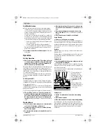
Page 12: ...ard6 to the required position Always adjust the protection guard 6 in such a manner that all 3 red cams of release lever 1 engage into the corresponding notches of the protection guard 6 Adjust the protection guard 6 in such a manner that sparking is prevented in the direction of the operator The protection guard 6 may be turned only upon actua tion of the release lever 1 Otherwise the power tool ...

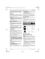
Page 13: ... the protection guard or oth er parts Flap Disc For operations with the flap disc always mount the hand guard 12 Rubber Sanding Plate For operations with the rubber sanding plate 13 al ways mount the hand guard 12 See graphics page for the mounting sequence Screw on the round nut 15 and tighten with the two pin span ner Cup Brush Disc Brush Foroperationswiththecupbrush wheelbrush always mount the ...

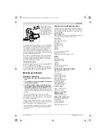
Page 14: ...atestrunforatleastoneminutewithnoload Do not use damaged out of centre or vibrating grind ing tools Damaged grinding tools can burst and cause in juries Working Advice Exercise caution when cutting slots in structural walls see Section Information on Structures Clamp the workpiece if it does not remain stationary due to its own weight Do not strain the machine so heavily that it comes to a standst...

Page 15: ...ertoolcanbeim paired Please store and handle the accessory ies carefully If the replacement of the supply cord is necessary this has to be done by Bosch or an authorized Bosch service agent in or der to avoid a safety hazard If the machine should fail despite the care taken in manufac turingandtestingprocedures repairshouldbecarriedoutby an after sales service centre for Bosch power tools Inallcor...

Reviews: