The following table allows initial estimates for the required cable cross-section for different
bus lengths and various numbers of bus participants.
Bus length (in m)
Number of devices on the CAN Bus
32
64
100
100
0.25 mm² or AWG24
0.34 mm² or AWG22
0.34 mm² or AWG22
250
0.34 mm² or AWG22
0.5 mm² or AWG20
0.5 mm² or AWG20
500
0.75 mm² or AWG18
0.75 mm² or AWG18
1.0 mm² or AWG17
Table 6.5: CAN BUS cable cross-section
If a participant cannot be directly connected to the CAN bus, a stub line (branch line) must be
used. Since there must always be precisely two terminating resistors on a CAN bus, a stub line
cannot be terminated. This creates reflections, which impair the rest of the bus system. To
minimize these reflections, these stub lines must not exceed a maximum individual length of
2 m at data transmission rates of up to 125 kbit/s, or a maximum length of 0.3 m at higher bit
rates. The overall length of all branch lines must not exceed 30 m.
The following applies:
–
In terms of rack wiring, standard RJ-45 patch cables with 100-ohm impedance (AWG 24/
AWG 26) can be used for short distances (up to 10 m).
–
The guidelines specified above for the network cabling must be used when wiring the
racks with each other and for the building installation.
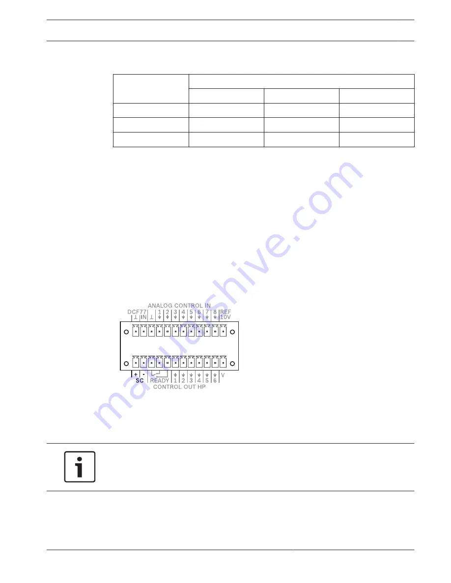
Slave clocks
The lower half of the control port has a special, short-circuit-proof output for polarity switch
impulses. Slave clocks connected here are automatically adjusted if a time difference is
detected between the slave clocks and the system clock, for example after a power failure or
in the event of manual input. Ensure that all slave clocks are connected with the same polarity.
Notice!
The maximum permissible number of slave clocks on the SC output depends on the power
consumption of the slave clock type used. Example: When using a slave clocks type with a
power consumption of 12 mA up to 80 slave clocks can be connected.
6.7
PAVIRO Controller
Connection | en
27
Operation manual
08-May-2017 | 04 | F01U306900


