English - 4
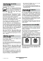
Remove the dust cover
17
.
After releasing the SDS lever for
base-plate adjustment
22
and
lightly pushing back the base
plate
7
, it can be tilted left or right to
a maximum of 45°.
The cutting angle can be pre-adjusted by means
of the scale for mitre angles
19
. Precise adjust-
ment with use of a commercial angle gauge
20
is
recommended.
After adjusting the base plate to the 0° or 45° po-
sition, slide the base plate toward the front (direc-
tion of the saw blade) to the stop.
To lock the base plate
7
, shut the SDS lever for
base-plate adjustment
22
.
With the thumbwheel for pre-tension of the base
plate
21
, the pre-tension of the SDS lever for
base-plate adjustment
22
can be adjusted. If the
base plate
7
is not seated tightly after shutting the
SDS lever, release the SDS lever
22
and rotate
the thumbwheel for pre-tension of the base
plate
21
in the “
+
” direction.
If the base plate
7
can not be adjusted or only
with difficulty after releasing the SDS lever for
base-plate adjustment
22
, rotate the thumbwheel
for pre-tension of the base plate
21
in the “
–
” di-
rection.
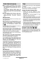
For sawing close to edges, the base plate can be
offset to the rear:
Remove the dust cover
17
.
Release the SDS lever for base-plate adjust-
ment
22
and slide the base plate toward the rear
to the stop.
If the base plate
7
can not be adjusted or only
with difficulty after releasing the SDS lever for
base-plate adjustment
22
, rotate the thumbwheel
for pre-tension of the base plate
21
in the “
–
” di-
rection.
To lock the base plate
7
, shut the SDS lever for
base-plate adjustment
22
. Possibly the thumb-
wheel for pre-tension of the base plate
21
must
be turned toward the “
+
” direction.
– With the base plate offset, only the 0° (normal)
position can be used.
– The circle cutter/parallel guide
24
as well as
the splinter guard
23
cannot be used in this
case.
The aluminium base plate
7
is equipped with a
steel insert for maximum stability. It is intended
for sawing of metal surfaces or insensitive mate-
rials without using the sliding shoe
8
.
When sawing materials that are easily scratched,
the sliding shoe
8
avoids scratching up sensitive
surfaces.
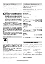
For mounting, insert the sliding shoe at the front
of the foot plate, lift at the rear and latch in.
To avoid fraying of the surface, press the splinter
guard with the notch facing upward
23
(as shown
in the figure) from below into the base plate
7
.
When working with the sliding shoe
8
, insert the
splinter guard
23
into the sliding shoe.
The splinter guard
23
can be inserted into the
base plate in 2 positions. For narrow saw blades,
insert the splinter guard fully to the front; for wider
saw blades, insert it further to the rear in the base
plate.
The splinter guard cannot be used for certain saw
blade types (e. g., saw blades with set teeth).
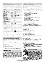
Adjusting the Cutting Angle
(see figure
)
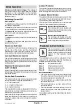
Offsetting the Base Plate
(see figure
)
C
D
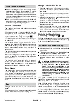
Sliding Shoe for Base Plate
(see figure
)
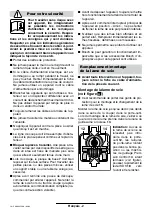
Splinter Guard (see figure
)
E
E
15 • 2 609 932 280 • 04.03

