background image

Safety

According Low Voltage Directive 73/23/EEC amended by Directive 93/68 EEC.

For European countries: according EN60065.Marking: CE

For international countries: IEC 60065 according B-Scheme.

For North America:
USA: ANSI/UL 60065
Canada: CAN/CSA no. 60065
Marking c-CSA-us.

Electro-magnetic compatibility

EMC compatibility:

According ECM Directive 89/336/EEC amended by Directive
93/68/ECC European approvals: CE marking EMC environment:
for commercial or professional use

EMC emission:

According harmonized standard EN 55103-1 (E3) (prof. audio/
video equipment). According FCC rules (FCC part 15) complying
to limits for class A digital devices

EMC immunity:

According harmonized standard EN 55103-2 (E3) (prof. audio/
video equipment). Immune to mobile phones
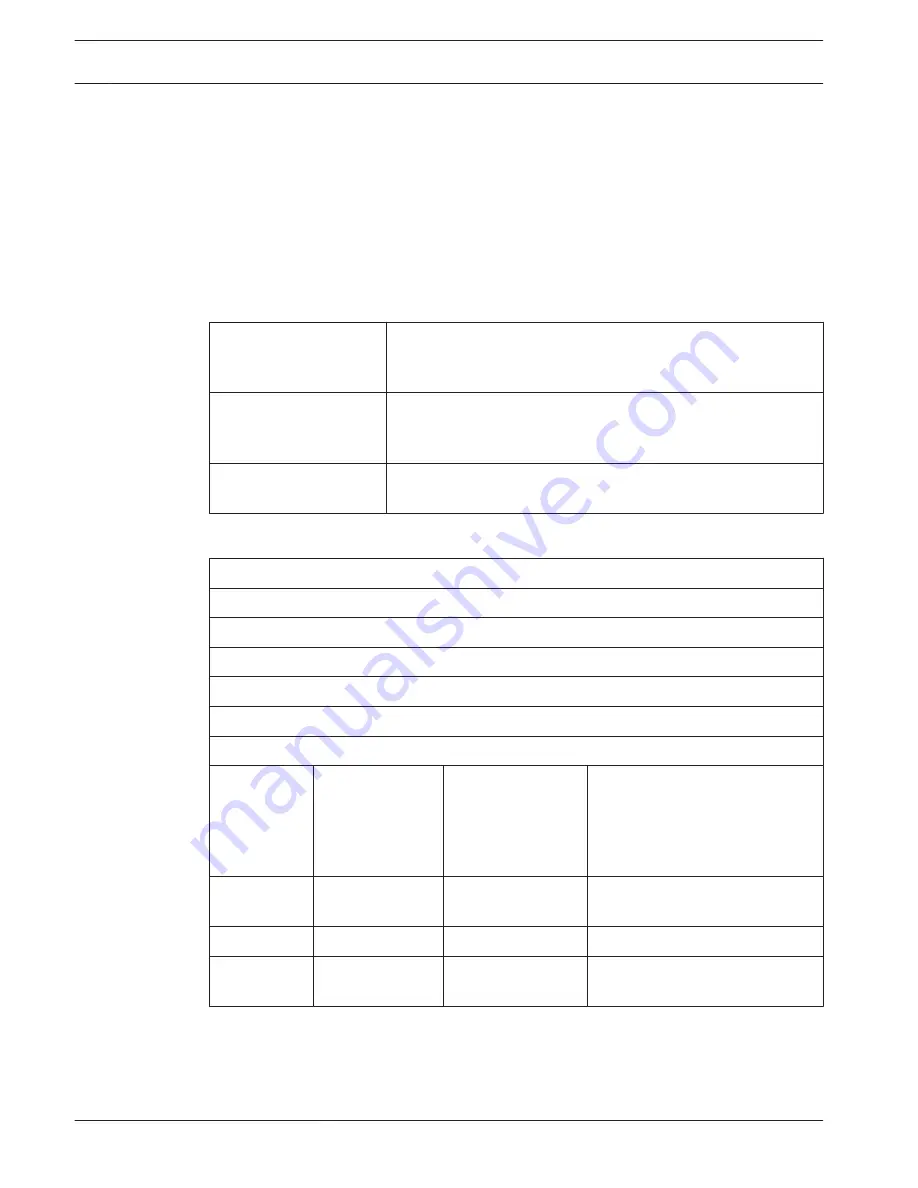
Wireless devices

Frequency

2400 - 2483.5 MHz

Max. transmitting power:

100 mW e.i.r.p.

Bandwidth:

22 MHz

Leading listed and certified country approvals:

Europe

CE
Standard

 
Telecom
EMC
 
Safety

 
EN 300 328EN 301 489-1EN 301
489-17EN 60950-1

USA

Standard

Telecom, EMCSafety FCC part 15.247

ANSI / UL 60950-1

Canada

Standard

Telecom, EMCSafety RSS 210CSA 22.2 no. 60950-1

Japan

Standard

Telecom, EMC

Ordinance regulating radio
equipment: Item 19 Article 2


11.1.3

11.1.4

11.1.5

270 en | Technical Data

Conference System

2013.11 | V2.0 | DCN-NG_OM_V4.x

Operation Manual

Bosch Security Systems B.V.

Summary of Contents for DCN Next Generation

Page 1: ...Conference System DCN Next Generation en Operation Manual ...

Page 2: ......

Page 3: ...N MICS Pluggable Microphones 36 3 12 DCN ICHS Intercom Handset 38 3 13 DCN FPT Flush Positioning Tool 39 3 14 DCN DDI Dual Delegate Interface 39 3 15 DCN FMIC Microphone Connection Panel 40 3 16 DCN FMICB Microphone Control Panel 41 3 17 DCN FPRIOB Priority Panel 41 3 18 DCN FLSP Loudspeaker Panel 42 3 19 DCN FV CRD Voting Panel 43 3 20 DCN FCS Channel Selector 44 3 21 DCN FVU Voting Unit 46 3 22 ...

Page 4: ...r length 80 4 2 7 Cable couplers 81 4 2 8 Bending Network Cable 81 4 2 9 Example layouts 83 4 3 Wireless network design 86 4 3 1 Limits 86 4 3 2 Frequency band 86 4 4 Wireless language distribution 88 4 5 CobraNet 88 4 6 User set up 89 4 6 1 Public areas 89 4 6 2 Speaking distance 89 4 6 3 Interpreter booths 89 4 7 Device set up 90 4 7 1 General 90 4 7 2 Cables 90 4 7 3 Temperature 90 4 7 4 Ventil...

Page 5: ...RD Voting Panel 135 6 18 DCN FCS Channel Selector 138 6 19 DCN FVU Voting Unit 141 6 20 DCN IDESK Interpreter Desks 141 6 21 DCN EPS Extension Power Supply 144 6 22 LBB4114 00 Trunk Splitter 146 6 23 LBB4115 00 Tap off unit 146 6 24 PRS NSP Network Splitter 146 6 25 PRS FINNA Fiber Interface 149 6 26 DCN DDB Data Distribution Board 151 6 27 Custom made Optical Network Cables 160 6 28 Custom made D...

Page 6: ...rity Panel 249 8 14 DCN FV CRD Voting Panel 250 8 15 DCN FVU Voting Unit 251 8 16 DCN IDESK Interpreter Desks 252 8 17 PRS NSP Network Splitter 255 8 18 PRS FINNA Fiber Interface 255 8 19 DCN DDB Data Distribution Board 255 9 Troubleshooting 259 9 1 System 259 9 2 DCN CCU2 and DCN CCUB2 Central Control Unit 261 9 3 DCN CON Concentus Unit 263 9 4 DCN DIS Discussion Unit 264 9 5 DCN WD Wireless Disc...

Page 7: ...Positioning Tool 282 11 2 14 DCN DDI Dual Delegate Interface 282 11 2 15 DCN FMIC Microphone Connection Panel 283 11 2 16 DCN FMICB Microphone Control Panel 283 11 2 17 DCN FPRIOB Priority Panel 283 11 2 18 DCN FLSP Loudspeaker Panel 283 11 2 19 DCN FV CRD Voting Panel 284 11 2 20 DCN FCS Channel Selector 284 11 2 21 DCN FVU Voting Unit 284 11 2 22 DCN FCOUP Couple 284 11 2 23 DCN FEC End Caps 284...

Page 8: ... NMB 003 du Canada The DCN wireless equipment has been tested and found to comply with the limits for a Class B digital device pursuant to Part 15 of the FCC Rules These limits are designed to provide reasonable protection against harmful interference in a residential installation This equipment generates uses and can radiate radio frequency energy and if not installed and used in accordance with ...

Page 9: ...xposure limits set forth for an uncontrolled environment The Wireless Discussion Units and the Wireless Access Point should be installed and operated with minimum distance of 20 cm to your body The RF parts of the Wireless Discussion Units and the Wireless Access Point must not be co located or operating in conjunction with any other antenna or transmitter Conference System Safety en 9 Bosch Secur...

Page 10: ... observed These signs from least severe effect to most severe effect are Notice Containing additional information Usually not observing a notice does not result in damage to the equipment or personal injuries Caution The equipment or the property can be damaged or persons can be lightly injured if the alert is not observed Warning The equipment or the property can be seriously damaged or persons c...

Page 11: ...ransformer 2 Distribution supply box 3 Conductive compartment trays 4 Electro static voltage sensor 5 Cotton overall 6 Conductive floor mat 7 Conductive boots heel grounding protectors 8 Conductive stool 9 Strap resistance 0 5 to 1 0 MΩ 10 Common reference point 11 Conductive bench top 12 Supply ground Table 2 1 ESD prevention 2 4 Conference System About this manual en 11 Bosch Security Systems B ...

Page 12: ... 1 cm 0 3937 in 1 ft 0 3048 m 1 m 3 281 ft 1 mi 1 609 km 1 km 0 622 mi Table 2 2 Conversion of units of length 1 lb 0 4536 kg 1 kg 2 2046 lb Table 2 3 Conversion of units of mass 1 psi 68 95 hPa 1 hPa 0 0145 psi Table 2 4 Conversion of units of pressure Notice 1 hPa 1 mbar F _ C 32 9 5 C _ F 32 5 9 2 5 12 en About this manual Conference System 2013 11 V2 0 DCN NG_OM_V4 x Operation Manual Bosch Sec...

Page 13: ...overview The DCN System comprises Central control units audio expanders Integrus transmitter and or wireless access point Wireless discussion units wired discussion units Consentus units flush mounted units and or interpreter desks Installation devices such as Dual Delegate Interfaces DDI and extension power supply units trunk splitters Notice Refer to the Integrus manual for all related informati...

Page 14: ...dio output 1 PA Audio output 2 Selectable recorder delegate loudspeaker mix minus insertion Interpreter floor insertion local floor 7 Power inlet Connects the central control unit to the mains power supply with a power cable 8 Ground screw Connects the central control unit to ground 9 Fuse holder Prevents damage to the internal power supply unit of the central control unit 10 Ethernet socket Conne...

Page 15: ... The following sections give more information about the mentioned subject Planning Planning page 64 Installation 19 inch units page 91 Connection 19 inch Units page 112 and DCN CCU2 and DCN CCUB2 Central Control Units page 113 Configuration 19 inch units page 179 and DCN CCU2 and DCN CCUB2 Central Control Units page 183 Operation DCN CCU2 and DCN CCUB2 Central Control Units page 231 Troubleshootin...

Page 16: ...D C Ɖ O O I D I 1 2 2 1 PC PC CCU Figure 3 3 Audio processing scheme DCN CCU2 or DCN CCUB2 Contribution device s Wireless discussion units wired discussion units Consentus units and or flush mounted units D D D Delegate Discussion unit microphones and loudspeakers Optical device s Central control units audio expanders Integrus transmitter and or wireless access point Interpretation device s Interp...

Page 17: ... control unit transmits a signal that can be connected to an external public address system The central control unit sets The volume signal level The bass signal level The treble signal level In the Delegate loudspeaker mode the audio input 2 signal of the central control unit is added to the floor signal Ɖ O D C D C Ɖ O O I D I 1 2 2 1 PC PC CCU Figure 3 4 Delegate loudspeaker Conference System S...

Page 18: ...central control unit Ɖ O D C D C Ɖ O O I D I 1 2 2 1 PC PC CCU Figure 3 5 Insertion Notice In the Insertion mode a device between audio output 2 and audio input 2 of the central control unit could be connected When no device is connected the audio signals from contribution devices floor leave the system but do not enter the system again 18 en System Overview Conference System 2013 11 V2 0 DCN NG_O...

Page 19: ...otice The Mix minus connection prevents acoustic feedback Ɖ O D C D C Ɖ O O I D I 1 2 2 1 PC PC CCU Figure 3 6 Mix minus Notice Use a telephone coupler in case of long distances between the two systems Conference System System Overview en 19 Bosch Security Systems B V Operation Manual 2013 11 V2 0 DCN NG_OM_V4 x ...

Page 20: ...ters can be delayed with an external device to lip sync it with the video plus improve S N ratio for systems with external floor and DCN interpretation Integrus The external device should be connected to output 2 and input 2 Ɖ O D C D C Ɖ O O I D I 1 2 2 1 PC PC CCU Figure 3 7 Interpreter floor insertion 20 en System Overview Conference System 2013 11 V2 0 DCN NG_OM_V4 x Operation Manual Bosch Sec...

Page 21: ... results in a 12dB lower audio level Ɖ O D C D C Ɖ O O I D I 1 2 2 1 PC PC CCU Figure 3 8 Insertion no AGC Local floor in Multi CCU sytems Local floor is applicable only for slave CCUs and is used to create directional sound In the Local floor mode audio output 2 of the central control unit only transmits the floor signal of the units connected to the DCN CCU2 In this way audio outputs 2 of the sl...

Page 22: ...Connects the audio expander to external devices Through the control inputs external devices can control the audio inputs and the audio outputs of the audio expander 5 Audio inputs Connects the audio expander to external analog audio sources 6 Audio outputs Connects the audio expander to external analog audio devices 7 Ground screw Connects the audio expander to ground 8 Optical network sockets Con...

Page 23: ...dio expander to external devices Through the control inputs external devices can control the audio inputs and the audio outputs of the audio expander 5 Ground screw Connects the digital audio expander to ground 6 Optical network sockets Connects the audio expander to the optical network 7 Control outputs Sends the condition of the audio expander to external devices 8 Audio inputs Connects the audi...

Page 24: ...Net network contains the audio inputs and the audio outputs of the cobranet interface 6 Control inputs Connects the cobranet interface to external devices Through the control inputs external devices can control the audio inputs and the audio outputs of the cobranet interface 7 Control outputs Sends the condition of the cobranet interface to external devices The following sections give more informa...

Page 25: ...nt 2 Optical network sockets Connects the wireless access point to the optical network The following sections give more information about the mentioned subject Installation DCN WAP Wireless Access Point page 92 Connection DCN WAP Wireless Access Point page 123 Configuration DCN WAP Wireless Access Point page 205 Operation DCN WAP Wireless Access Point page 244 Troubleshooting DCN WAP Wireless Acce...

Page 26: ...ons to a conference With the Concentus Chairman Unit DCN CONCM the chairman can monitor and control a conference 7 6 1 2 3 7 8 6 5 1 2 3 4 7 6 5 1 2 3 DCN CON DCN CONFF DCN CONCS Figure 3 13 Top views 3 6 26 en System Overview Conference System 2013 11 V2 0 DCN NG_OM_V4 x Operation Manual Bosch Security Systems B V ...

Page 27: ...9 10 11 11 10 DCN CONCS DCN CONFF Figure 3 14 Side views Conference System System Overview en 27 Bosch Security Systems B V Operation Manual 2013 11 V2 0 DCN NG_OM_V4 x ...

Page 28: ...enabled the signal of the loudspeaker is muted 3 Microphone LED Is on when the microphone is enabled 4 Card reader Gives access to the Concentus delegate unit 5 Channel selector Selects the channel that is sent to the headphones 6 Microphone button Enables or disables the microphone The microphone button has a LED that shows the condition of the microphone 28 en System Overview Conference System 2...

Page 29: ... Concentus unit does not have an address The only difference between the Concentus chairman unit and the Concentus delegate unit is the priority button on the left of the microphone button Figure 3 17 Priority and microphone buttons With the priority button the chairman can disable the microphones of all delegate devices At the same time the priority button enables the microphone of the chairman T...

Page 30: ... DCN DISCS DCN WDCS 3 6 DCN DISD DCN WDD 1 2 3 1 2 3 15 15 15 Figure 3 18 Top views 1 wired and wireless 1 2 3 15 15 15 6 1 2 3 5 6 7 5 3 5 4 4 4 1 2 3 6 7 DCN DISDCS DCN WDDCS DCN DISVCS DCN WDVCS DCN DISV DCN WDV Figure 3 19 Top views 2 wired and wireless 3 7 30 en System Overview Conference System 2013 11 V2 0 DCN NG_OM_V4 x Operation Manual Bosch Security Systems B V ...

Page 31: ... Side views wired or wireless 15 11 Figure 3 21 Rear view wireless units 10 9 Figure 3 22 Rear view wired units Conference System System Overview en 31 Bosch Security Systems B V Operation Manual 2013 11 V2 0 DCN NG_OM_V4 x ...

Page 32: ...ireless units 12 3 2 1 13 14 Figure 3 24 Bottom view wired units 15 3 2 1 13 14 Figure 3 25 Bottom view 2 wireless units 32 en System Overview Conference System 2013 11 V2 0 DCN NG_OM_V4 x Operation Manual Bosch Security Systems B V ...

Page 33: ...n has a yellow LED The LED adjacent to voting button 1 is the attendance LED 8 Headphones socket Headphone connection 9 DCN cable Connects the discussion unit wired to the DCN 10 DCN socket Makes a loop through in the DCN with the discussion unit 11 Status LEDs Gives information about the condition of the wireless discussion unit 12 Screw holes Attach the wired discussion unit to a flat surface 13...

Page 34: ... The battery pack contains 1 Capacity LEDs Show the capacity of the battery pack 2 Clip Locks the battery pack in for example a wireless discussion unit The following sections give more information about the mentioned subject Operation DCN WLIION Battery Pack page 247 Maintenance DCN WLIION Battery Pack page 268 Technical Data DCN WLIION Battery Pack page 280 3 8 34 en System Overview Conference S...

Page 35: ...er supply 5 Power inlet Mains power supply connection 6 Loop through socket Connects the battery charger to another battery charger with a power cable The following sections give more information about the mentioned subject Installation DCN WCH05 Battery Charger page 101 Connection DCN WCH05 Battery Charger page 131 Operation DCN WCH05 Battery Charger page 248 Technical Data DCN WCH05 Battery Char...

Page 36: ...crophones are used with the contribution and interpretation devices Type Length mm DCN MICS 310 DCN MICL 480 Table 3 1 Types and lengths 1 2 3 Figure 3 28 Overview 3 11 36 en System Overview Conference System 2013 11 V2 0 DCN NG_OM_V4 x Operation Manual Bosch Security Systems B V ...

Page 37: ...microphone to devices The following sections give more information about the mentioned subject Connection DCN MICL DCN MICS Pluggable Microphones page 132 Operation DCN MICL DCN MICS Pluggable Microphones page 248 Technical data DCN MICL DCN MICS Pluggable Microphones page 281 Conference System System Overview en 37 Bosch Security Systems B V Operation Manual 2013 11 V2 0 DCN NG_OM_V4 x ...

Page 38: ...om handset 6 1 Figure 3 30 Intercom plug RJ11 connection Type Description DCN CON Concentus Delegate Unit DCN CONCS Concentus Channel Selector Unit DCN CONFF Concentus Full Function Unit DCN CONCM Concentus Chairman Unit DCN DDI Dual Delegate Interface Table 3 2 Compatible devices The following sections give more information about the mentioned subject Technical Data DCN ICHS Intercom Handset page...

Page 39: ...itioning Tool page 282 DCN DDI Dual Delegate Interface Use the DCN DDI Dual Delegate Interface to connect contribution devices with flush mounted devices 8 7 1 3 2 4 6 5 Figure 3 32 Dual delegate interface The dual delegate interface contains 1 DCN cable Connects the dual delegate interface to the DCN 2 Mode selector Sets the mode in which the dual delegate interface operates 3 Intercom socket Con...

Page 40: ... Panel connects DCN MICL and DCN MICS Pluggable Microphones to the DCN DDI Dual Delegate Interface 2 3 1 Figure 3 33 Microphone connection panel The microphone connection panel contains 1 Output level plug Connects the microphone connection panel to a DCN FCS Channel Selector to prevent acoustic feedback 2 Microphone socket Connects a DCN MICL or DCN MICS Pluggable Microphone to the microphone con...

Page 41: ... FPRIOB Priority Panel With the DCN FPRIOB Priority Panel the chairman can disable the microphones of all delegate devices The priority panel must be used with the DCN DDI Dual Delegate Interface in the chairman mode 1 Figure 3 35 Priority panel The priority panel contains 1 Priority button Disables the microphones of all delegate devices and enables the microphone of the chairman device when it i...

Page 42: ...r Gives the audio signal from the floor to the delegate or chairman The following sections give more information about the mentioned subject Installation DCN Flush mounted products page 103 Connection DCN FLSP Loudspeaker Panel page 135 Technical Data DCN FLSP Loudspeaker Panel page 283 3 18 42 en System Overview Conference System 2013 11 V2 0 DCN NG_OM_V4 x Operation Manual Bosch Security Systems...

Page 43: ...e Refer to the following table for the available types Type Description DCN FVCRD Voting panel with card reader DCN FV Voting panel without card reader Table 3 3 Types 1 2 Figure 3 37 Top view DCN FV 1 3 2 Figure 3 38 Top view DCN FVCRD 3 19 Conference System System Overview en 43 Bosch Security Systems B V Operation Manual 2013 11 V2 0 DCN NG_OM_V4 x ...

Page 44: ...ockets Connects the voting panel to the DCN DDI Dual Delegate Interface and the DCN FMICB Microphone Control Panel The following sections give more information about the mentioned subject Installation DCN Flush mounted products page 103 Connection DCN FV CRD Voting Panel page 135 Technical Data DCN FV CRD Voting Panel page 284 DCN FCS Channel Selector With the DCN FCS Channel Selector delegates an...

Page 45: ... the DCN system with the channel selector 8 Level reduction plug Reduces the headphone signal level when the microphone of a connected device is enabled 9 Solder spots 10 External headphones solder pads Connect an external headphones socket to the channel selector The following sections give more information about the mentioned subject Installation DCN Flush mounted products page 103 Connection DC...

Page 46: ... overview of the different types Type Description DCN FVU Standard version DCN FVU CN Chinese version Table 3 4 Types 1 2 Figure 3 43 Front view DCN FVU 1 2 Figure 3 44 Front view DCN FVU CN 3 21 46 en System Overview Conference System 2013 11 V2 0 DCN NG_OM_V4 x Operation Manual Bosch Security Systems B V ...

Page 47: ...the voting unit to the DCN 5 DCN socket Makes a loop through in the DCN with the voting unit 6 External contact plug Connects the voting unit to an external contact 7 Solder spot Configures the external contact plug The following sections give more information about the mentioned subject Installation DCN Flush mounted products page 103 Connection DCN FVU Voting Unit page 141 Operation DCN FVU Voti...

Page 48: ...CN FCOUP Couple page 284 and DCN FEC End Caps page 284 DCN FEC End Caps Use the DCN FEC End Caps to install flush mounted devices Figure 3 48 End cap The following sections give more information about the mentioned subject Installation DCN Flush mounted products page 103 Technical Data DCN FEC End Caps page 284 3 22 3 23 48 en System Overview Conference System 2013 11 V2 0 DCN NG_OM_V4 x Operation...

Page 49: ...CN FBP panels Use the DCN FBP Flush Blank Panel or the DCN FBPS Flush Blank Panel Short to temporarily close recesses refer to DCN FBP panels page 285 Figure 3 50 Flush blank panel The following sections give more information about the mentioned subject Installation DCN Flush mounted products page 103 Technical Data DCN FBP panels page 285 3 24 3 25 Conference System System Overview en 49 Bosch Se...

Page 50: ...or the conference Floor a b c d e A B Auto relay Micro Mute Engaged Phone Intercom Help Slow Chair Call 1 2 13 14 15 16 17 18 19 20 21 12 11 3 6 9 8 7 10 4 5 Figure 3 51 Top view 22 23 24 Figure 3 52 Left view 3 26 50 en System Overview Conference System 2013 11 V2 0 DCN NG_OM_V4 x Operation Manual Bosch Security Systems B V ...

Page 51: ...6 Microphone socket Connects a DCN MICL or DCN MICS Pluggable Microphone to the interpreter desk 7 Telephone LED Is on when the interpreter desk receives a phone call from an external telephone system 8 Intercom LED Is on when the interpreter desk receives an intercom call 9 Message button Opens closes channel overview status Opens text messages that are sent to the interpreter desk When the inter...

Page 52: ...peak slowly signaling Depending on the system the interpreter will send a signal to a DCN DDB Data Distribution Board to activate a connected indicator or to the DCN SW DCN Conference SW In case a DCN DDB is used the connected indicator will be active as long as the interpreter holds the speak slowly button down In case the DCN SW Conference SW is used both software modules DCN SWSMD and DCN SWSI ...

Page 53: ...DCN IDESK Interpreter Desks page 108 Connection DCN IDESK Interpreter Desks page 141 Configuration DCN IDESK Interpreter Desks page 221 Technical Data DCN IDESK Interpreter Desks page 285 DCN EPS Extension Power Supply The DCN EPS Extension Power Supply supplies power to the DCN system Use it to increase the number of devices that can be connected to the system Notice The DCN EPS UL Extension Powe...

Page 54: ... DCN EPS Extension Power Supply page 226 Technical Data DCN EPS Extension Power Supply page 286 LBB4114 00 Trunk Splitter Use the LBB4114 00 Trunk Splitter to divide the DCN trunk 1 2 4 3 Figure 3 57 Top and side views 1 DCN socket tap off 1 Makes a tap off in the DCN system The socket regenerates the DCN signal 2 DCN socket tap off 2 Makes a tap off in the DCN system The socket regenerates the DC...

Page 55: ...00 Tap off unit page 110 Connection LBB4115 00 Tap off unit page 146 Technical Data LBB4115 00 Tap off unit page 286 LBB4116 Extension Cables The following extension cable assembly products are available Type number Cable length LBB4116 02 2 m LBB4116 05 5 m LBB4116 10 10 m LBB4116 15 15 m LBB4116 20 20 m LBB4116 25 25 m LBB4116 00 100 m Table 3 5 Extension cables Except for LBB4116 00 all extensi...

Page 56: ... LBB4117 00 Cable Locking Clamps with the LBB4119 00 DCN Connectors LBB4118 00 Cable Termination Plug Use an LBB4118 00 Cable Termination Plug to close an open ended DCN cable e g for voting units with two cables or a spare or expansion cable Figure 3 60 Cable termination plug 3 31 3 32 56 en System Overview Conference System 2013 11 V2 0 DCN NG_OM_V4 x Operation Manual Bosch Security Systems B V ...

Page 57: ...d contains a label with an explanation about the internal settings 5 Status LED A yellow LED that gives information about the condition of the network splitter 6 Status LED A green LED that gives information about the condition of the network splitter 7 Optical network socket tap off 2 Makes a tap off in the optical network The socket has a maximum load of 2 5 A that gives protection against short...

Page 58: ...e fiber interface to a POF 3 Status LED A yellow LED that gives information about the condition of the fiber interface 4 Status LED A green LED that gives information about the condition of the fiber interface 5 GOF socket Connects the fiber interface to a GOF The following sections give more information about the mentioned subject Installation PRS FINNA Fiber Interface page 111 Connection PRS FIN...

Page 59: ...tical fibers to transmit data and two copper wires to supply the power Figure 3 63 Optical network cable E1 O1 O2 E2 Figure 3 64 Optical network connector connection 3 35 Conference System System Overview en 59 Bosch Security Systems B V Operation Manual 2013 11 V2 0 DCN NG_OM_V4 x ...

Page 60: ... 100 m Table 3 6 Optical network cables Except for LBB4416 00 all optical network cables have optical network connectors Use the LBB4417 00 Optical Network Connectors to make cables from LBB4416 00 Optical Network Cable 100 m with the LBB4418 00 Cable connector Tool Kit Figure 3 66 LBB4417 00 Optical Network Connectors Refer to System page 259 Optical network problems for further information 60 en...

Page 61: ...ting system with Allen key 600 004 0 2 Cable cutter 600 015 36 3 Crimping tool 642 509 3 23 4 POF positioning crimping tool 618 071 69 5 Stripping tool 607 202 69 6 POF cutter stripping tool 600 003 1 39 7 Torx screwdriver C209 000077 Table 3 7 Tool kit contents Tool kit supplier Rennsteig Werkzeuge GmbHViernau Thüringen GermanySupplier type number 600 100 PHI 3 36 Conference System System Overvie...

Page 62: ...f the data distribution board 1 DCN cable Connects the data distribution board to the DCN 2 J10 jumper block Selects the power supply of the data distribution board 3 S8 switches Configure the data distribution board 4 RS232 port To connect the data distribution board to a hall display 5 Parallel inputs connector To make remote controls 6 Parallel inputs solder pads To make remote controls 7 Paral...

Page 63: ...ith the DCN IDCRD Chip Cards delegates and chairmen can identify themselves to the system Use the chip cards to give the delegates and chairmen access to The microphones of the contribution devices The voting functions on the contribution devices The intercom functions on the contribution devices Figure 3 70 ID card Notice Use the DCN IDENC ID card Encoder to configure the ID cards Notice Labels t...

Page 64: ...sive devices is without limit refer to Control capacity page 66 The maximum number of data distribution boards in the system is 15 Limit 2 Power capacity The maximum power that one DCN socket of the central control unit can supply is 85 W Refer to section Power capacity page 67 Limit 3 Loop through The maximum number of loop throughs in succession for active devices is 25 where 4 m additional exte...

Page 65: ...tions The maximum number of tap off connections in succession between the central control unit and the last tap off in a branch is four If there are more than four tap off connections in succession the system does not operate correctly Limit 5 Cable lengths With regenerative tap offs the maximum cable length is 250 m from the central control unit to the furthest device in any branch of the DCN The...

Page 66: ...ows the active and passive devices in the DCN Device Type DCN CON Active DCN CONCS Active DCN CONFF Active DCN CONCM Active DCN DDB Passive Active DCN DDI Active DCN DISL Active DCN DISS Active DCN DISCS Active DCN DISD Active DCN DISDCS Active DCN DISV Active DCN DISVCS Active DCN EPS Passive DCN FCS Passive DCN FVU Active DCN FVU CN Active DCN IDESK Active LBB4114 00 Passive LBB4115 00 Passive T...

Page 67: ...DCN DDB 2 0 DCN DDI 4 5 LBB4114 00 1 3 LBB4115 00 1 4 Table 4 2 Power consumption Notice The power consumption of the DCN DDI includes the power consumption of all flush mounted devices that you can connect to it Power supplies The devices that supply power to the DCN are the central control unit and the extension power supply The power that the central control unit supplies includes the power tha...

Page 68: ...igher than shown in the figure an overload situation will occur DCN CCUB2 P 85 W P 85 W P 85 W DCN CCUB2 Figure 4 2 DCN power supply DCN CCUB2 DCN EPS P 85 W P 85 W P 85 W DCN EPS Figure 4 3 DCN power supply DCN EPS 68 en Planning Conference System 2013 11 V2 0 DCN NG_OM_V4 x Operation Manual Bosch Security Systems B V ...

Page 69: ...nsate for the extension cables Calculation To find the correction for each DCN socket of the central control unit and the extension power supply with the graph you must first calculate The total power consumption of the devices that are connected to the socket The length of the longest extension cable sequence Total power consumption Do as follows 1 Find the power consumption of each device from t...

Page 70: ...ws 1 Find the total power consumption as explained in the previous chapter Total power consumption on the vertical axis Y of the power correction graph For example 40 W 2 Find the length of the longest extension cable sequence on the horizontal axis X of the power correction graph For example 60 m 3 The intersection of both values gives the necessary power from the socket In this example it is 53 ...

Page 71: ... DISS DCN DISS DCN DISS DCN DISS LBB4114 00 LBB4114 00 7x 7x 7x 7x 5 m Figure 4 5 Example with discussion units DCN DISS Socket Extension cable Power for devices Corrected power Trunk 1 40 m 69 9 W 83 9 W Trunk 2 20 m 76 8 W 83 8 W Trunk 3 15 m 79 6 W 84 9 W Table 4 3 Example with discussion units DCN DISS The example above is within system limits because 4 1 7 Conference System Planning en 71 Bos...

Page 72: ... this example is 7 DCN limit 4 maximum tap off connections is not exceeded The limit is 4 the highest number of loop through connections in the example is 1 DCN limit 5 maximum cable length is not exceeded The limit is 250m the longest distance from the central control unit to the furthest device in this example is only 51m Conference devices 10 m 10 m 15 m 10 m 10 m LBB4114 00 LBB4114 00 LBB4114 ...

Page 73: ...e limit is 25 the highest number of loop throughs in this example is 6 DCN limit 4 maximum tap off connections is not exceeded The limit is 4 the highest number of loop through connections in the example is 1 DCN limit 5 maximum cable length is not exceeded The limit is 250 m the longest distance from the central control unit to the furthest device in this example is only 51 m DCN CCU2 or DCN CCUB...

Page 74: ...m 2 m 100 m 1 10 LBB4114 LBB4116 10 x 4 5 1 x 1 3 45 0 W 1 3 W 46 3 W 79 4 W DCN FCS 0 m 40 x 2 m 2 m 50 x 2 m 90 51 LBB4114 50 1 90 x 0 9 1 x 1 3 81 0 W 1 3 W 82 3 W 82 3 W DCN FCS 100 m 50 x 2 m 2 m 100 m 1 50 LBB4114 LBB4116 50 x 0 9 1 x 1 3 45 0 W 1 3 W 46 3 W 79 4 W Table 4 5 DCN CCU2 or DCN CCUB2 power correction examples 74 en Planning Conference System 2013 11 V2 0 DCN NG_OM_V4 x Operation...

Page 75: ...sk becomes defective the defective desk can have an effect on all other interpreter desks that have a connection to the same trunk LBB4114 00 Figure 4 7 Interpreter booths with LBB4114 00 With an LBB4115 00 Protected Trunk Splitter you can connect two interpreter desks If an interpreter desk becomes defective the defective desk has no effect on all other interpreter desks that have a connection to...

Page 76: ...LBB4115 00 LBB4115 00 LBB4115 00 Figure 4 8 Interpreter booths with LBB4115 00 76 en Planning Conference System 2013 11 V2 0 DCN NG_OM_V4 x Operation Manual Bosch Security Systems B V ...

Page 77: ...tical network is 1 Limit 3 Cables The maximum length of the standard network cable LBB4416 xx Plastic Optical Fiber cable is 50 m If longer cables are required the PRS FINNA can be used to convert from plastic to glass and vice versa The total maximum cable length of Glass Optical Fiber GOF plus the Plastic Optical Fiber POF is dependent on the total length of GOF and POF plus the equivalent cable...

Page 78: ...er Interface Non Addressable 0 16 PRS NSP Network Splitter 1 34 LBB4419 00 Cable Couplers 0 20 INT TX04 Digital 4 Channel Integrus Transmitter 1 18 INT TX08 Digital 8 Channel Integrus Transmitter 2 24 INT TX16 Digital 16 Channel Integrus Transmitter 4 36 INT TX32 Digital 32 Channel Integrus Transmitter 8 59 Table 4 6 Nodes Power capacity It is important that the devices in the optical network do n...

Page 79: ...iber Interface refer to PRS FINNA Fiber Interface page 58 DCN CCU2 The central control unit supplies power to The optical network The DCN sockets For an overview of the maximum power that the central control unit can supply refer to the figure 1 2 3 P 85 W P 85 W P 85 W P 65 W DCN CCU2 Figure 4 9 Optical network power supply DCN CCU2 If the DCN CCU2 is configured as a master CCU in a multi CCU sys...

Page 80: ...optical attenuation the maximum length of optical network cables LBB4416 is 50 m You can use GOF and fiber interfaces to increase the distance between devices to more than 50 m and less than 1500 m refer to PRS FINNA Fiber Interface page 58 The total sum of the used Plastic Optical Fiber plus the Glass Optical Fiber plus the equivalent cable length of the used devices should not exceed 2090 For ex...

Page 81: ...ical attenuation Each cable coupler decreases the maximum distance between two devices in the optical network normally 50 meters with 20 meters Bending Network Cable The minimum bend radius of a 90 degree bend in an LBB4416 cable is 110 mm A 180 degree bend is the same as two 90 degree bends R 110 mm Figure 4 11 Bend radius Coiling The minimum coiling radius of an LBB4416 cable is 110 mm 4 2 7 4 2...

Page 82: ...R 110 mm Figure 4 12 Coiling radius 82 en Planning Conference System 2013 11 V2 0 DCN NG_OM_V4 x Operation Manual Bosch Security Systems B V ...

Page 83: ...tended optical network The below figure is an example of a extended optical network DCN CCU2 LBB4404 00 INT TX PRS 4DEX4 DCN WAP Figure 4 14 Extended optical network Redundant optical network If the cable between the central control unit DCN CCU2 and the audio expander LBB4402 00 breaks the central control unit cannot transmit data to the audio expander A solution for this problem is to use a redu...

Page 84: ...f all devices in the redundant optical network is 85 W If the optical network is defective near the central control unit the other socket can supply power to all of the optical network Tap offs The network splitter PRS NSP lets you make tap offs Tap offs cannot be redundant If the cable between the network splitter and the digital audio expander PRS 4DEX4 becomes defective the digital audio expand...

Page 85: ... it is not required to close the optical ring as shown in figure 4 16 however closing it makes it redundant as explained in the chapter regarding Redundant optical network Notice In case the Multi CCU system contains only 2 CCUs and no PC control is required the network switch can be omitted The network cable can go from the CCU that is assigned as master directly to the CCU assigned as slave A cr...

Page 86: ...uage Distribution Channels only the first 10 channels will be available for the wireless network All higher channels will only be available for the wired DCN network and or the infrared Integrus network Frequency band 802 11g specification The wireless network is based on the 802 11g specification for WiFi technology Devices that comply to the 802 11g specification operate in frequency bands betwe...

Page 87: ...2 427 2 432 2 437 2 442 2 447 2 452 2 457 2 462 2 467 2 472 2 484 GHz 2 400 Figure 4 19 DCN wireless carriers 1 0 1 2 2 3 4 5 6 7 8 9 10 11 12 13 2 412 GHz 2 417 2 422 2 427 2 432 2 437 2 442 2 447 2 452 2 457 2 462 2 467 2 472 2 484 GHz 2 400 Figure 4 20 Example of interference Conference System Planning en 87 Bosch Security Systems B V Operation Manual 2013 11 V2 0 DCN NG_OM_V4 x ...

Page 88: ...facturers of professional audio devices support the CobraNet standard The DCN System can connect to CobraNet networks with the LBB4404 00 Cobranet Interface For example you can use the LBB4404 00 Cobranet Interface to Benefit from Ethernet infrastructure Transport audio signals over large distances PC data for example data from the DCN System Open Interface can co exist with CobraNet data on the s...

Page 89: ...s Integrus receivers Acoustic feedback between the connected headphones or headsets and the microphone occurs when The volume level is set too high The headphones are too close to enabled microphones You must tell the users to keep sufficient distance from the microphones or not to set the volume level higher than is necessary Refer to section Acoustic feedback page 90 Speaking distance The recomm...

Page 90: ... rack make sure there is rack space between the devices to let sufficient airflow Forced airflow may be necessary to keep the temperature of the devices below the maximum temperature refer to section Product Technical Data page 276 This extends the lifetime of the devices Ventilation Keep a good airflow Airflow holes are in the front right and left sides of all 19 inch devices for example the cent...

Page 91: ... Four feet and two brackets are supplied with the central control unit Figure 5 1 Installation Notice The central control unit extends 36 mm in front of the brackets when installed in a rack system 5 5 1 Conference System Installation en 91 Bosch Security Systems B V Operation Manual 2013 11 V2 0 DCN NG_OM_V4 x ...

Page 92: ...cates invalid Only qualified personnel may open the wireless access point Wall or ceiling Use the bracket to attach the wireless access point to a wall or ceiling 02 01 TORX 10 Figure 5 2 Installation wall and ceiling 5 2 92 en Installation Conference System 2013 11 V2 0 DCN NG_OM_V4 x Operation Manual Bosch Security Systems B V ...

Page 93: ...to install the wireless access point on an LBC1259 00 Universal Floor stand 02 01 Figure 5 3 Installation LBC1259 00 Conference System Installation en 93 Bosch Security Systems B V Operation Manual 2013 11 V2 0 DCN NG_OM_V4 x ...

Page 94: ...o The orientation of the logo could be changed 02 01 TORX 10 Figure 5 4 Installation of the logo 94 en Installation Conference System 2013 11 V2 0 DCN NG_OM_V4 x Operation Manual Bosch Security Systems B V ...

Page 95: ...uipment Contact your supplier in case this equipment is used as stationary equipment in a North American country 20 mm Figure 5 5 Install the Concentus in a recess When you install the Concentus unit in a recess use the following template to make the correct contour 5 3 Conference System Installation en 95 Bosch Security Systems B V Operation Manual 2013 11 V2 0 DCN NG_OM_V4 x ...

Page 96: ...stance between the centres of the screw holes is 100 mm DCN DIS and DCN WD Discussion units General Caution Do not open the wireless discussion unit Any hardware change makes the product certificates invalid Only qualified personnel may open the wireless discussion unit Rims With a rim the look of the discussion unit can be changed The discussion units are supplied without rims Attach a DCN DISR R...

Page 97: ...hone buttons The mode of the discussion unit refer to DCN DIS and DCN WD discussion units page 208 indicates the type and number of microphone buttons that must be installed Conference System Installation en 97 Bosch Security Systems B V Operation Manual 2013 11 V2 0 DCN NG_OM_V4 x ...

Page 98: ...ts page 208 Refer to the following figure how to remove microphone buttons from a discussion unit Figure 5 9 Remove microphone buttons Refer to the following figure to install microphone buttons Figure 5 10 Install microphone buttons DCN DIS Discussion Units wired You can move the DCN cable from the rear side to the bottom side of the discussion unit 98 en Installation Conference System 2013 11 V2...

Page 99: ... install the discussion unit desk in a recess Use the template Move the DCN cable to the bottom side of the discussion unit Notice When you install the discussion unit in a recess make sure that the delegates or the chairman can connect the headphones When you attach the discussion unit to a flat surface put screws with a length of 8 mm in the screw holes no 12 The distance between the centres of ...

Page 100: ... 8 4x 0 5 0 R73 8 2x 0 5 0 R7498 8 2x 2 0 117 6 0 3 0 Figure 5 13 Template refer to the DVD that is supplied with the system for a dwg file 100 en Installation Conference System 2013 11 V2 0 DCN NG_OM_V4 x Operation Manual Bosch Security Systems B V ...

Page 101: ...ges from the battery charger can kill you Caution Do not obstruct the ventilation grilles A blockage of the ventilation grilles can cause a risk of fire Wall You can use the bracket to attach the battery charger to a wall 5 5 Conference System Installation en 101 Bosch Security Systems B V Operation Manual 2013 11 V2 0 DCN NG_OM_V4 x ...

Page 102: ...etween two brackets is at least 340 mm refer to d1 in the figure The horizontal distance between two brackets is at least 195 mm refer to d2 in the figure d2 d1 Figure 5 16 Installation multiple battery chargers Battery Figure 5 17 Installation battery 102 en Installation Conference System 2013 11 V2 0 DCN NG_OM_V4 x Operation Manual Bosch Security Systems B V ...

Page 103: ... of a recess depends on the number size factor NSF of the flush mounted device that must be installed in the recess To get the length of a recess Get the number size factor NSF of the flush mounted device Use the NSF to get the length x of the recess from the table Total NSF x mm 1 38 2 2 88 2 Table 5 1 Lengths snap mounting method Block mounting Use the block mounting method to install flush moun...

Page 104: ...04 03 01 02 TORX 8 TORX 8 Figure 5 20 Example block mounting method 104 en Installation Conference System 2013 11 V2 0 DCN NG_OM_V4 x Operation Manual Bosch Security Systems B V ...

Page 105: ...unting method 3 3 0 0 5 0 x 0 5 0 R2 5 0 5 0 5 Figure 5 22 Recess block mounting method The length x of a recess depends on the total number size factor NSF of the flush mounted devices that must be installed in the recess To calculate the length of a recess For each flush mounted device get the number size factor NSF Conference System Installation en 105 Bosch Security Systems B V Operation Manua...

Page 106: ...21 5 Table 5 2 Lengths block mounting method Number size factor The length of a recess depends on The number of flush mounted devices that are installed in the recess The size of the flush mounted devices that are installed in the recess To calculate the length of a recess you must use the number size factor NSF refer the table of the flush mounted devices Flush mounted device NSF DCN FCS 2 DCN FL...

Page 107: ...l the flush mounted devices in the tabletop housing You can attach the tabletop housing to a flat surface with M3 screws Notice You can temporarily close the tabletop housing with a DCN FBP Flush Blank Panel 101 92 30 11 5 56 97 5 6 4x 113 Figure 5 23 Bottom view Conference System Installation en 107 Bosch Security Systems B V Operation Manual 2013 11 V2 0 DCN NG_OM_V4 x ...

Page 108: ...ion When you install the interpreter desk in a flat surface use the template Notice When you install the interpreter desk in a recess make sure that the interpreter can connect the headphones or the headset 5 7 108 en Installation Conference System 2013 11 V2 0 DCN NG_OM_V4 x Operation Manual Bosch Security Systems B V ...

Page 109: ...he extension power supply in a 19 inch rack system or on a flat surface Two brackets are supplied with the extension power supply Notice You can only install the extension power supply in a 19 inch rack system together with a second extension power supply A B Figure 5 26 Installation 5 8 Conference System Installation en 109 Bosch Security Systems B V Operation Manual 2013 11 V2 0 DCN NG_OM_V4 x ...

Page 110: ...0 Tap off unit Refer to LBB4114 00 Trunk Splitter page 110for information about the installation of the LBB4115 00 Protected Trunk Splitter The procedures to install the LBB4114 00 Trunk Splitter and the LBB4115 00 Protected Trunk Splitter are the same 5 9 5 10 110 en Installation Conference System 2013 11 V2 0 DCN NG_OM_V4 x Operation Manual Bosch Security Systems B V ...

Page 111: ...attach or remove the unit from the bracket PRS FINNA Fiber Interface Refer to PRS NSP Network Splitter page 111 for information about the installation of the fiber interface The procedures to install the network splitter and the fiber interface are the same 5 11 5 12 Conference System Installation en 111 Bosch Security Systems B V Operation Manual 2013 11 V2 0 DCN NG_OM_V4 x ...

Page 112: ... socket of the audio expander The headphones must have a 3 5 mm plug 2 3 1 Figure 6 2 3 5 mm headphones plug connection Number Signal 1 Left 2 Common 3 Right Table 6 1 3 5 mm headphones plug connection Notice You can also connect mono headphones to the headphones socket You can select the signal that is available on the headphones socket with the configuration menu refer to DCN CCU2 and DCN CCUB2 ...

Page 113: ...cable clamps to lock DCN cables to the central control unit Each DCN socket has a red LED that comes on if there is an overload Audio inputs You can connect an external analog audio source to the audio inputs of the central control unit The DCN CCU2 has two audio inputs Each audio input has 1 XLR socket for balanced signals The electric circuits behind the XLR sockets contain transformers for galv...

Page 114: ...ess system to the audio outputs of the central control unit The DCN CCU2 has two audio outputs Each audio output has 1 XLR plug for balanced signals The electric circuits behind the XLR plugs contain transformers for galvanic separation 1 double cinch socket for unbalanced signals The CCUB2 has two audio outputs One audio output has 1 XLR plug for balanced signals 1 double cinch socket for unbalan...

Page 115: ...nected The central control unit internally connects the Fail pins when The central control unit is stopped The internal power supply unit operates incorrectly The central control unit does a reset The central control unit is downloading or reset to defaults OK Fail Figure 6 6 Fault contact Ethernet socket Use the Ethernet socket to connect a PC Use Cat5e cable or better Figure 6 7 Ethernet socket ...

Page 116: ... Receive Data 3 TxD Transmit Data 4 DTR Data Terminal Ready 5 SG Signal Ground 6 DSR Data Set Ready 7 RTS Request To Send 8 CTS Clear To Send 9 RI Ring Indicator Table 6 4 RS232 port connection 116 en Connection Conference System 2013 11 V2 0 DCN NG_OM_V4 x Operation Manual Bosch Security Systems B V ...

Page 117: ...f the audio expander You can connect microphone sources only to the XLR socket of audio input 1 and audio input 2 of the audio expander Use the configuration menu to configure the audio inputs of he audio expander refer to LBB4402 00 Audio Expander page 191 Notice When the interlock mode is None refer to DCN IDESK Interpreter Desks page 221 the audio inputs of the digital audio expander are disabl...

Page 118: ...e the configuration menu to configure the audio outputs of the audio expander refer to LBB4402 00 Audio Expander page 191 Control inputs The audio expander has eight control inputs With the control inputs remote interpretation systems can control the audio inputs and the audio outputs of the audio expander Each audio input and audio output has a control input Control In 1 2 3 4 5 6 7 8 Figure 6 11...

Page 119: ...ol outputs connection With the control outputs you can Send the condition of the audio outputs to external devices control output 1 2 3 and 4 Send the condition of the connection of the optical network to external devices control output 5 When an audio output is assigned to an individual microphone channel a corresponding contact can be switched when the level is above threshold Refer to LBB4402 0...

Page 120: ...ckets contain transformers 1 cinch socket for SPDIF signals Notice You cannot use the AES EBU and SPDIF connections of the same audio input at the same time In 1 Out 1 AES EBU SPDIF 2 3 4 1 5 Figure 6 13 Audio input connection Pin Type Signal Description 1 XLR Xternal Shield ground 2 Live Positive 3 Return Negative 4 Cinch Live Signal in 5 Return Shield ground Table 6 9 Audio input connection Noti...

Page 121: ...ription 1 XLR Xternal Shield ground 2 Live Positive 3 Return Negative 4 Cinch Live Signal in 5 Return Shield ground Table 6 10 Audio input connection Each audio output can contain a maximum of 2 channels L and R The digital audio expander does not change stereo signals in mono signals Use the configuration menu to configure the audio outputs of the digital audio expander refer to PRS 4DEX4 Digital...

Page 122: ...tances PC data for example data from the DCN System Open Interface can co exist with CobraNet data on the same Ethernet network when you use managed Ethernet switches that are approved by Peak Audio Notice Refer to the CobraNet info website www cobranet info for More data about CobraNet networks A list of approved Ethernet switches Connect the cobranet interface to the CobraNet network with UTP ca...

Page 123: ...put channels can route to floor channels Control inputs and outputs The cobranet interface has eight control inputs and five control outputs With the control inputs remote systems can control the cobranet interface With the control outputs you can send the condition of the cobranet interface to external devices The control inputs and outputs of the audio expander and the cobranet interface do the ...

Page 124: ...ophone plug connection When you connect a headset to the DCN CONFF or DCN CONCM unit you must connect the microphone of the headset to the external microphone socket The Concentus unit senses that an external microphone is connected to the external microphone socket The Concentus delegate unit internally disconnects the DCN MICL or DCN MICS Pluggable Microphone if connected Headphones You can conn...

Page 125: ...gate unit The intercom handset must be connected to the RJ45 socket 1 8 Figure 6 19 RJ45 socket connection Pin Signal 1 Headphones level reduction 2 Microphone ground 3 Microphone in 4 Earpiece positive 5 Earpiece ground 6 Hook switch 7 Hook switch 8 External contact Table 6 15 RJ45 socket connection Notice The DCN ICHS Intercom Headset has a RJ11 plug This plug fits in the center of the RJ45 sock...

Page 126: ... of the RJ45 socket Notice The external contact is only available in systems that operate with a control PC that has one or more of these software modules Parliamentary Voting software module Multi Voting software module Attendance Registration software module Message Distribution Refer to the applicable Software User Manuals for the instructions that tell you how to use the external contact R 0 5...

Page 127: ...s acoustic feedback RJ45 DCN CON DCN FCS 1 2 3 4 5 6 7 8 1 2 Figure 6 21 Channel selector connection When the microphone that is connected to the Concentus delegate unit is enabled the channel selector automatically decreases the volume level of the signal that is sent to the headphones of the channel selector Conference System Connection en 127 Bosch Security Systems B V Operation Manual 2013 11 ...

Page 128: ...ice You can move the DCN cable from the rear side to the bottom side of the discussion unit refer to DCN DIS and DCN WD Discussion units page 96 You can use the cable to unit clamps to lock DCN cables to discussion units 2 1 Figure 6 22 Cable to unit clamp 6 8 128 en Connection Conference System 2013 11 V2 0 DCN NG_OM_V4 x Operation Manual Bosch Security Systems B V ...

Page 129: ...ery Pack in the wireless discussion unit 02 01 Figure 6 23 Install a battery pack When you remove the battery pack from the wireless discussion unit you can connect the wireless discussion unit to a DCN WPS Power Supply Adapter 6 9 Conference System Connection en 129 Bosch Security Systems B V Operation Manual 2013 11 V2 0 DCN NG_OM_V4 x ...

Page 130: ...evices The DCN WPS Power Supply for WDU is not USB compliant and will damage your device You can change the power plug of the power supply adapter Figure 6 25 Installing power plug 130 en Connection Conference System 2013 11 V2 0 DCN NG_OM_V4 x Operation Manual Bosch Security Systems B V ...

Page 131: ...u can connect a maximum of 5 battery chargers If the power supply is 220 240 V AC 50 60 Hz you can connect a maximum of 10 battery chargers Figure 6 27 Loop through socket Battery To charge the DCN WLIION battery pack you have to insert it in the DCN WCH05 battery charger Figure 6 28 Inserting a battery pack 6 10 Conference System Connection en 131 Bosch Security Systems B V Operation Manual 2013 ...

Page 132: ...ure 6 29 Microphone plug connection Pin Signal 1 Indicator ring red cathode 2 Indicator ring common anode 3 Microphone signal 4 Microphone GND 5 Shielding 6 Indicator ring green cathode Table 6 17 Microphone plug connection 6 11 132 en Connection Conference System 2013 11 V2 0 DCN NG_OM_V4 x Operation Manual Bosch Security Systems B V ...

Page 133: ... 2 Not used 3 Table 6 18 3 5 mm loudspeaker plug connection Typically you will connect DCN FLSP Loudspeaker Panels refer to DCN FLSP Loudspeaker Panel page 42 to the audio outputs Intercom outputs You can connect an DCN ICHS Intercom Handset to the dual delegate interface The intercom handset must be connected to the intercom socket Voting Control inputs You can use the voting control inputs to co...

Page 134: ... Microphone on LED 5 to 7 Request to speak LED 6 to 7 Momentarily microphone switch Table 6 20 Connections Typically you will connect DCN FMIC Microphone Connection Panels refer to DCN FMIC Microphone Connection Panel page 40 to the audio inputs For information about configuration of the DCN DDI Dual Delegate Interface refer to DCN DDI Dual Delegate Interface page 213 134 en Connection Conference ...

Page 135: ...ou can connect for example an AMP173977 2 socket to the output level plug of the microphone connection panel DCN FMICB Microphone Control Panel A Cat 4 cable with RJ11 plugs is supplied with the microphone connection panel Use this cable to connect the panel to the DCN DDI Dual Delegate Interface or DCN FV CRD Voting Panel DCN FPRIOB Priority Panel A Cat 4 cable with RJ11 plugs is supplied with th...

Page 136: ...e 6 21 External contact connection Notice You can connect for example an AMP173977 3 socket to the external contact plug of the voting panel Use the solder spot refer to DCN FV CRD Voting Panel page 43 no 5 to configure the external contact plug With the solder spot you can configure the galvanic separation of pin 3 and the ground of the external contact plug Solder spot Description Not soldered P...

Page 137: ...the figure for a circuit diagram of an external contact connection that does not use the galvanic separation On PCB External 5V DC 1 3 R 2 X6 0 5 m Figure 6 36 External contact connection 2 Conference System Connection en 137 Bosch Security Systems B V Operation Manual 2013 11 V2 0 DCN NG_OM_V4 x ...

Page 138: ...phones socket to the channel selector e g a 6 3 mm headphones socket The external headphones socket must be connected to a plug or to solder pads X18 X17 X16 Figure 6 37 External headphones connection 1 3 2 1 Figure 6 38 External headphones connection 2 The solder pads and the plug are internally connected 6 18 138 en Connection Conference System 2013 11 V2 0 DCN NG_OM_V4 x Operation Manual Bosch ...

Page 139: ...evel reduction plug When the channel selector is used with a device that has a microphone acoustic feedback can occur Use the level reduction plug to prevent acoustic feedback 1 2 Figure 6 39 Output level plug connection Pin Signal 1 Positive 2 GND Table 6 24 Output level plug connection Notice You can connect for example an AMP173977 2 socket to the level reduction plug of the channel selector Co...

Page 140: ...e devices have a output level plug that you can connect to the level reduction plug of the channel selector DCN CON Concentus Delegate Unit DCN CONCS Concentus Delegate Unit DCN CONFF Concentus Delegate Unit DCN CONCM Concentus Chairman Unit DCN FMIC Microphone Connection Panel 140 en Connection Conference System 2013 11 V2 0 DCN NG_OM_V4 x Operation Manual Bosch Security Systems B V ...

Page 141: ...t the interpreter desk to the DCN with the DCN cable You can use the DCN socket to make a loop through with the interpreter desk Headset You can connect a headset to the headset socket of the interpreter desk The headset socket refer to DCN IDESK Interpreter Desks page 50 must be IEC 268 11 compliant with a 5 pole 180 DIN plug 3 5 4 2 1 Figure 6 40 Headset socket connection Pin Signal 1 Microphone...

Page 142: ...nterpreter desk An external telephone system to the telephone LED of the interpreter desk 1 8 Figure 6 43 External devices socket connection Pin Function Description 1 2 Booth on air Pin 2 and 3 are closed when booth on air 3 4 5 Telephone Positive in 6 Telephone Negative in 7 Intercom Positive in 8 Intercom Negative in Table 6 28 External devices socket connection Contact rating for the booth on ...

Page 143: ...levels for telephone and intercom contacts no call 1 V DC call 3 V DC max 24 V DC Galvanic separated Conference System Connection en 143 Bosch Security Systems B V Operation Manual 2013 11 V2 0 DCN NG_OM_V4 x ...

Page 144: ... that the fuse holder on the rear of the extension power supply contains the correct fuse refer to DCN EPS Extension Power Supply page 226 3 Connect a locally approved power cable to the extension power supply Out Out Out In Tap off Trunk Out Out Out In Tap off Trunk Figure 6 44 Power supply 4 Connect the power cable to a locally approved mains power supply Notice Make sure that the mains power su...

Page 145: ...age 78 DCN tap offs With the DCN tap off sockets you can make tap offs in the DCN Mains Out Out In Tap off Trunk Out Out Out In Tap off Trunk Figure 6 46 DCN tap offs Each DCN tap off socket has a red LED that comes on if there is an overload refer to Power capacity page 78 Conference System Connection en 145 Bosch Security Systems B V Operation Manual 2013 11 V2 0 DCN NG_OM_V4 x ...

Page 146: ... the optical network with the optical network sockets tap off 2 trunk 7 8 2 3 tap off 1 trunk Figure 6 48 Optical network Notice If the distance between two devices is less than 100 m use a network splitter between devices to remove the use of fiber interfaces Use only the trunk sockets of the network splitter in this case Power supply You can connect an external power supply to the external power...

Page 147: ... KPP 4P plug connection Notice You can for example connect a DCN EPS Extension Power Supply to the Kycon KPP 4P socket of the network splitter The Kycon KPP 4P plug is shown in parts A B C D E G F semi circular notch arm H I slot slotted cut out metal tabs U section Figure 6 50 Kycon KPP 4P plug parts Conference System Connection en 147 Bosch Security Systems B V Operation Manual 2013 11 V2 0 DCN ...

Page 148: ...ch the Plastic Ring Guide E to the Lower Metal Sleeve H and engage the plastic arms into the correct slots in the sides of the sleeve 9 Attach the Top Metal Cover F to Lower Metal Sleeve H Be sure to align all tabs Make sure that the cover is attached correctly 10 Push the Metal Spring D to the Top Metal Cover F Lower Metal Sleeve H assembly This helps to hold the assembly together 11 Push the Str...

Page 149: ...of fiber interfaces Use only the trunk sockets of the network splitter in this case The GOF socket is a double SC socket that uses invisible infra red light 1300 nm Tx Rx Figure 6 52 Double SC socket connection Pin Signal Tx Transmitter Rx Receiver Table 6 31 Double SC socket connection This figure is an example of a GOF cable with a double SC plug Figure 6 53 GOF with double SC plug Make sure tha...

Page 150: ...rning For safety reasons you must use a current limited external power supply complying with the 60065 standard for audio video usage or equivalent with a maximum output current of 5A or you must use an external fuse 5A max slow in the wiring to the Kycon KPP 4P connector Max 48V 5A KPP 4P Pin 1 KPP 4P Pin 2 Figure 6 54 Power supply connection 150 en Connection Conference System 2013 11 V2 0 DCN N...

Page 151: ...it Data 4 Not connected 5 SG Signal Ground 6 Not connected 7 RTS Request To Send 8 CTS Clear To Send 9 Not connected Table 6 32 RS232 port connection Speak slowly signaling The interpreter desks refer to DCN IDESK Interpreter Desks page 50 have a speak slowly button With this button the interpreters can activate an indicator that tells the current speaker to speak slowly This function of the inter...

Page 152: ...I 125 mA I 125 mA V 50 V DC Figure 6 56 Physical connections Notice The parallel outputs are also available on a 20 pole connector refer to DCN IDESK Interpreter Desks page 50 Refer to the figure for a circuit diagram for speak slowly signaling 152 en Connection Conference System 2013 11 V2 0 DCN NG_OM_V4 x Operation Manual Bosch Security Systems B V ...

Page 153: ...e maximum number of activated parallel outputs is eight D00 to D07 Help signaling The interpreter desks DCN IDESK have a Help button With this button the interpreters can activate an indicator that tells the operator or chairman that they need assistance This function of the interpreter desk must always be used along with the data distribution board Refer to the figure for the physical connections...

Page 154: ... I 125 mA I 125 mA I 125 mA I 125 mA I 125 mA I 125 mA I 125 mA V 50 V DC Figure 6 58 Physical connections Notice The parallel outputs are also available on a20 pole connector refer to DCN IDESK Interpreter Desks page 50 Refer to the figure for a circuit diagram for help signaling 154 en Connection Conference System 2013 11 V2 0 DCN NG_OM_V4 x Operation Manual Bosch Security Systems B V ...

Page 155: ...s 255 Power supply You can connect an external power supply to the power supply connector The external power supply only gives power to the data distribution board It does not give power to the DCN Supply voltage DCN or external 10 40 V DC Current consumption DCN 50 mA 40 V DC Table 6 33 Power supply You can enable or disable the connected external power supply with the J10 jumper block Position P...

Page 156: ...ple to switch on lamps open doors or close curtains in the room Notice The parallel inputs and parallel outputs are also available on a 20 pole connector All parallel inputs and parallel outputs form pairs For example parallel input U00 controls parallel outputs D00 156 en Connection Conference System 2013 11 V2 0 DCN NG_OM_V4 x Operation Manual Bosch Security Systems B V ...

Page 157: ...e associated parallel outputs on all other data distribution boards that are In the passive mode and do not have address 253 254 or 255 Notice Do not use a parallel output for more than one purpose For example parallel input D00 of a distribution board does not only control parallel output U00 of the same data distribution board It also controls all the parallel output U00 of all the other data di...

Page 158: ...5V U08 U09 U10 U11 U12 U13 U14 U15 Reserved GND Figure 6 62 Parallel inputs Refer to the figure for the physical connections of the parallel outputs 158 en Connection Conference System 2013 11 V2 0 DCN NG_OM_V4 x Operation Manual Bosch Security Systems B V ...

Page 159: ...125 mA I 125 mA I 125 mA Reserved Figure 6 63 Parallel outputs Refer to the figure for a circuit diagram to connect the parallel inputs On PCB _ VC D00 D07 D08 D15 I 125 mA GND V 50 V DC Figure 6 64 Circuit diagram Conference System Connection en 159 Bosch Security Systems B V Operation Manual 2013 11 V2 0 DCN NG_OM_V4 x ...

Page 160: ...ables 7 0 1 3 2 1 5 4 Figure 6 65 Wires Number Signal 1 Protective cloth 2 Insulation 3 Outer sheet 4 Stranded wire 5 Optical fiber Table 6 36 Wires The optical network connector LBBB4417 00 has 10 parts 6 27 160 en Connection Conference System 2013 11 V2 0 DCN NG_OM_V4 x Operation Manual Bosch Security Systems B V ...

Page 161: ...make the cable connector The procedure has these parts Prepare Remove the ends from the copper wires Attach the socket contacts Remove the ends from the optical fibers Attach the ferrules Assemble the connector Crimp the bush Conference System Connection en 161 Bosch Security Systems B V Operation Manual 2013 11 V2 0 DCN NG_OM_V4 x ...

Page 162: ... length Notice Light decreases in intensity through the length of the cable The length of an optical network cable must be less than 50 m 2 Examine the cable type Some steps in the procedure change because of the cable type 3 Disassemble an optical network connector An optical network connector has 10 parts 4 Push the cable through the back housing Figure 6 69 Back housing on cable 5 Push the cabl...

Page 163: ...nto a hexagonal shape Before you crimp the bush make sure that both plastic optical fibers are parallel to a flat side of the hexagonal cross section A B A R B B R B R Red Brown R B Figure 6 71 Cross section transformation 2 Use the crimping tool tool 3 to attach the crimping bush to the outer sheath The crimping bush stops the cable from rotating in the connector Conference System Connection en 1...

Page 164: ...ut the copper wires at position II with the cable cutter tool 2 II I Figure 6 73 Cutting a copper wire 2 Push the copper wires to the mechanical stop of the stripping tool tool 5 Remove the red and brown insulations from the copper wires 164 en Connection Conference System 2013 11 V2 0 DCN NG_OM_V4 x Operation Manual Bosch Security Systems B V ...

Page 165: ...crimping tool tool 3 The upper part of the crimping tool contains a ridge to put the socket contact correctly in the tool Figure 6 75 Crimping a socket contact 1 Figure 6 76 Crimping a socket contact 2 Conference System Connection en 165 Bosch Security Systems B V Operation Manual 2013 11 V2 0 DCN NG_OM_V4 x ...

Page 166: ...able connector mounting procedure A B Figure 6 78 Mounted socket contacts Remove the sheath from the optical fibers Proceed as follows 1 Put the plastic optical fibers into the POF cutter stripping tool tool 6 The optical fiber that is to be cut must be put in the small guide hole The other optical fiber must be put in the large guide hole Push the cable until the crimping bush is against the stop...

Page 167: ... 80 Cutting a fiber 2 2 Close the tool to hold the cable and pull the trigger to cut the optical fiber Figure 6 81 Cutting a fiber 3 Conference System Connection en 167 Bosch Security Systems B V Operation Manual 2013 11 V2 0 DCN NG_OM_V4 x ...

Page 168: ...sheath Notice Do not forget to remove the piece of sheath from the tool 6 Repeat steps 17 and 18 for the other fiber in the cable Refer to the figure to see the result of this part of the cable connector mounting procedure A B Figure 6 83 Stripped optical fibers Attach the ferrules Do as follows 1 Put a ferrule into the spring loaded stop of the POF positioning crimping tool tool 4 168 en Connecti...

Page 169: ... lock the ferrule Figure 6 85 Locking a ferrule 3 Put one plastic optical fiber into the ferrule in the spring loaded stop of the POF positioning tool Conference System Connection en 169 Bosch Security Systems B V Operation Manual 2013 11 V2 0 DCN NG_OM_V4 x ...

Page 170: ...cal plastic fiber The next step crimps the ferrules on the sheaths of the fibers 6 Put both ferrules in the crimping tool tool 3 Figure 6 87 Crimping ferrules 2 7 Crimp the ferrules on the sheath using the crimping tool tool 3 Refer to the figure for the result of this part of the cable connector assembly procedure 170 en Connection Conference System 2013 11 V2 0 DCN NG_OM_V4 x Operation Manual Bo...

Page 171: ... upper part of the connector the optical fibers will be attached to the lower part of the connector refer to Figure 5 42 Notice When replacing a connector always first check the wiring in the connector at the other end E1 O1 O2 E2 Figure 6 90 Front view of connector Refer to the wiring diagram and the figures Pin Signal Wire E1 48V DC Copper E2 GND Copper Conference System Connection en 171 Bosch ...

Page 172: ...tails E1 RED E1 BROWN E2 O1 BLACK 2x O2 E2 O1 O2 Figure 6 91 Wiring diagram O1 O2 O1 O2 A A E1 E2 E1 E2 R R B B R B Red Brown Figure 6 92 Wiring diagram applied to type A optical network cables 172 en Connection Conference System 2013 11 V2 0 DCN NG_OM_V4 x Operation Manual Bosch Security Systems B V ...

Page 173: ... of cable is shown in the figures Do as follows 1 Make sure the ends of the cables and the plastic optical fibers correct A B A B R B B R R B R B R B Red Brown Figure 6 94 Copper wires and fibers 2 Put the ferrules in the mounting block A B Figure 6 95 Mounting block and back housing Conference System Connection en 173 Bosch Security Systems B V Operation Manual 2013 11 V2 0 DCN NG_OM_V4 x ...

Page 174: ...R R B Red Brown Figure 6 96 Mounting block and back housing 4 Put the mounting block in the back housing Figure 6 97 Mounting block back housing assembly 5 Click the front housing on the mounting block back housing assembly Figure 6 98 Mounting the front housing 6 Insert the Torx screw into the front housing 174 en Connection Conference System 2013 11 V2 0 DCN NG_OM_V4 x Operation Manual Bosch Sec...

Page 175: ...x screwdriver tool 7 Figure 6 100 Tightening the Torx screw 8 Put the dust cap on the connector to protect the plastic optical fibers Figure 6 101 Dust cap on connector Conference System Connection en 175 Bosch Security Systems B V Operation Manual 2013 11 V2 0 DCN NG_OM_V4 x ...

Page 176: ...cket 1 6 2 3 4 5 5 6 4 3 2 1 Figure 6 103 DCN plug and socket connection 1 5 2 4 3 6 GND Figure 6 104 DCN cable connection Pin Signal Color 1 Downlink GND 2 Downlink data Green 3 40 V DC Brown 4 Uplink data White 5 Uplink GND 6 40 V DC Blue Table 6 38 DCN cable connection 6 28 176 en Connection Conference System 2013 11 V2 0 DCN NG_OM_V4 x Operation Manual Bosch Security Systems B V ...

Page 177: ...aster CCU to the PC 4 Select Download CCU 5 Select Download optical devices 6 Power off the master CCU and the optical devices 7 Connect the CCUs one at a time to the PC 8 Select Download CCU 9 Power off the CCUs one at a time Notice The Download and License Tool can be used for upgrading When Download Optical devices is selected all applicable devices connected to the optical network will be upgr...

Page 178: ...vice for more than one second to erase the address and do the initialization at the same time All LEDs of the wireless discussion unit come ON and the LED around the microphone indicator ring comes ON as red The old subscription is erased and the unit is ready for subscription Caution Do not use a sharp object otherwise you might damage the de init switch Use a paperclip or similar device to push ...

Page 179: ...Most menu items have one or more parameters To make adjustments change the values of the parameters VU meter Some menu items have a VU meter The VU meter shows the volume levels of signals The VU meter has seven rows VU meter Description One row on No signal Seven rows on Maximum signal Triangle Clipped signal Minus Disabled by control input Table 7 1 VU meter To open the main menu To open the mai...

Page 180: ... the applicable parameter push the knob to select the parameter The display shows a cursor To change the value of a parameter Do as follows 1 Select the applicable parameter 2 Turn the knob to move the cursor to the value 3 Push the knob The value flashes 4 Turn the knob to go to the value 5 When the display shows the correct value push the knob to select the value The display shows a cursor To cl...

Page 181: ...is reached 5 Push the knob to go to the sub menu 6 Push the knob to open the sub menu item 7 Turn the knob to move the cursor to the value that is shown 8 On the value push the knob 9 Turn the knob to change the value Notice In this example the knob is turned counterclockwise to decrease the value from 0 dB to 6 dB Turn the knob clockwise to increase the value Conference System Configuration en 18...

Page 182: ...main menu number 12 Push the knob to go back to the main menu 13 Turn the knob clockwise to go to the Back menu item 14 Push the button to go to the main screen 182 en Configuration Conference System 2013 11 V2 0 DCN NG_OM_V4 x Operation Manual Bosch Security Systems B V ...

Page 183: ... 7Ad 7Ae 7Af 7B 7Ba HW Version 7Bb FPGA Version 7Bc 7Bd 8Fa Repetition 8Fb WAP Mode 8Fc Encryption 8Aa Mic Priority 8Ab Request LED 8Ac Auto Mic Off 8Da Operator 8Db Chairman 8Ga Level 8Gb Routing I O2 8A 8B Att tones Floor Distr Microphone 8D 8E 8Ia Address 8Ib Subnet Mask 8Ic Def Gateway 8N Reset to Defaults 8F Wireless Del Display Intercom 8G Audio I O 8H Camera Contr 8I IP Address 8J CCU Mode ...

Page 184: ...e Table 7 2 Microphone sub menu default Refer to the next table for the microphone priority settings Value Description Permanently off The system does not activate the microphones of the delegates again when the chairman releases the priority button The requests to speak and speakers are erased Temporarily off The system activates the microphones of the delegates again when the chairman releases t...

Page 185: ...m handset of the operator to identify the location of the operator 8Db Assign Chairman No Yes Does not start the assign chairman procedure Starts the assign chairman procedure Lift the receiver of the intercom handset of the chairman to identify the location of the chairman Table 7 6 Intercom sub menu default Delegate display Use the menu item in the 8E Del Display sub menu to set the display lang...

Page 186: ... 4 0 or higher have a default encryption key Wireless Discussion Units with older versions or with changed encryption keys can not be subscribed and can therefore not be used with a DCN CCU2 that has the default key and has encryption enabled The encryption key of the DCN CCU2 and Wireless Discussion Units can be changed with the Download License Tool delivered on the DVD that came with the centra...

Page 187: ...ntrl sub menu to select the type of connected camera system Value Description Autodome The central control unit sends the camera control signal to a Bosch Autodome Baudrate 9 6 K Allegiant The central control unit sends the camera control signal to a Bosch Allegiant Baudrate 19 2 K Table 7 10 Camera control sub menu values default IP address Use the menu items in the 8I IP Address sub menu to set ...

Page 188: ...servers automatically handout new IP addresses from time to time This is not preferred for a multi CCU system renewing the CCU IP addresses will cause temporary disconnections between CCUs and cause improper system behavior With the enquiry menu 7Af the current IP Address of a CCU can be found In case DHCP is not available use menu 8Ia to give each CCU within the same subnet a unique Static IP add...

Page 189: ...L Double Unit ID is not applicable for wireless units Unit Hostname Some networks are able to handle hostnames In these networks the unique CCU hostnames can be used as well Use the 8M Unit Hostname sub menu item to set the name of the central control unit The unit name is also used as hostname in a TCP IP network The name of the central control unit is maximum 16 characters and only consists char...

Page 190: ...ts all parameters to the default values This includes the values of the parameters of the interpreter desks the IP settings and Unit Hostname The CCU is also restarted Table 7 15 Defaults sub menu default 190 en Configuration Conference System 2013 11 V2 0 DCN NG_OM_V4 x Operation Manual Bosch Security Systems B V ...

Page 191: ...Menu item Figure 7 3 Configuration menu Notice When the interlock is None refer to NoTrans Variables the audio inputs of the audio expander are disabled for translation channels only Audio input channels can route to floor channels Setup Use the 4 Setup menu item to open the Setup sub menu Use the menu items in this sub menu to configure the audio expander Notice To open the Setup sub menu you mus...

Page 192: ...hat is attached to the audio input or audio output of the audio expander PA public address system 4E Ctrl Thresh Signal Output 1 Output 2 Output 3 Output 4 Level 60 to 10 dB 60 to 10 dB 60 to 10 dB 60 to 10 dB When an output is assigned to an individual microphone channel the corresponding contact is switched when the level is above threshold 4F Unit Name Name Analog Expander Custom name The name ...

Page 193: ...al level of the received interpretations is 9 dBV XLR 6 dBV cinch When the nominal input of an external interpretation is high the audio of the external interpretations will be too loud compared to the audio of the internal interpretations from the interpreter desks Notice When channel 00 is assigned to an audio input the system automatically disables AGC for the audio input You cannot manually en...

Page 194: ...quiry Setup Back 1 Fault Status Main 4C Routing 4B Output Mode 4A AGC 4D Unit Name 4E Contact Thresholds 4F Defaults 4 Menu item with sub menu Menu item Figure 7 4 Configuration menu Source modes Use the menu items in the 2C Source Mode sub menu to view the formats of the digital audio on the audio inputs of the digital audio expander 7 5 194 en Configuration Conference System 2013 11 V2 0 DCN NG_...

Page 195: ... 2L Input 2R AGC On Off On Off On Off On Off Sets the automatic gain control AGC of the audio inputs on and off 4B Output Mode Output Output 1 Output 2 Format AES EBU SPDIF AES EBU SPDIF The format of the digital audio for audio output 1 and audio output 2 4C Routing Input output Input 1L Input 1R Input 2L Input 2R Output 1L Output 1R Output 2L Output 2R Channel 00 to 31 00 to 31 00 to 31 00 to 31...

Page 196: ...he interpreter desks Notice When channel 00 is assigned to an audio input the system automatically disables AGC for the audio input You cannot manually enable AGC for an audio input to which channel 00 is attached Notice If two systems are connected by audio connections Cobranet AEX or DEX set the AGC to off LBB4404 00 Cobranet Interface With the CobraNet Discovery you can Find the IP addresses of...

Page 197: ...m with sub menu Menu item Figure 7 5 Configuration menu Setup Use the 4 Setup menu item to open the Setup sub menu Use the menu items in this sub menu to configure the cobranet interface Notice To open the Setup sub menu you must push and hold the knob for more than 3 seconds Conference System Configuration en 197 Bosch Security Systems B V Operation Manual 2013 11 V2 0 DCN NG_OM_V4 x ...

Page 198: ...e Description 4D Reset to defaults No Yes Does not put back the default values Sets all parameters to the default values The name is not changed Table 7 21 Defaults sub menu default Automation gain control AGC Use the AGC menu item to enable or disable the AGC of the audio inputs If necessary enable the AGC for the audio inputs that inject external interpretations in the system The AGC makes sure ...

Page 199: ...tomatically gives IP addresses to new CobraNet devices You can set the range of automatically given IP addresses with the Start and End fields Notice When you remove the checkmark from the Enable Auto Assignment box you will get access to the Start and End fields Firmware Normally the firmware does not need updating If you do have to update the firmware you must use the database location on the PC...

Page 200: ...s the name and the firmware version of the CobraNet device 5 errorCount Shows the number of errors of the CobraNet device since you started CobraNet Discovery To decrease the width of a column 1 Click and hold the left mouse button on the right boundary of the column header 2 Move the mouse to the left to decrease the width of the column 3 Release the left mouse button To increase the width of a c...

Page 201: ...network Bundles The CobraNet network uses bundles for the transport of audio signals The CobraNet interface can Receive 4 bundles from the CobraNet network Rx Send 4 bundles to the CobraNet network Tx Receiver bundles Each receiver bundle can have 8 bundle channels To the bundle channels of a receiver bundle you can connect the audio inputs of the CobraNet interface Thus the audio inputs take audi...

Page 202: ...io outputs take audio signals from the optical network and send them to the CobraNet network Do as follows to configure a transmitter bundle of the CobraNet interface 1 Lauch the Transmitter configuration dialog from the main Configuration dialog by highlighting the line containing the transmitter information and then pressing the Configure button or by double clicking on the line containing the t...

Page 203: ... to receive this bundle it will be multicast else it will be unicast Multicast over 2 If more than two receivers are set to receive this bundle then it will be multicast else it will be unicast or multi unicast Multicast over 3 If more than three receivers are set to receive this bundle then it will be multicast else it will be unicast or multi unicast Multicast over 4 If more than four receivers ...

Page 204: ...le channels Figure 7 11 Configuration window Notice You can connect an audio output to more than one bundle channel When you connect an audio output to more than one bundle channel the system operates correctly 2 Enter the values of the other parameters of the transmitter bundle 3 Repeat step 4 to 6 for the other bundle channels in the transmitter bundle 204 en Configuration Conference System 2013...

Page 205: ...nu item Adjacent systems must have different system identities and different carriers 8J CCU Mode 12 01 Standalone 8J CCU Mode 03 01 Standalone 8J CCU Mode 08 01 Standalone Figure 7 12 System IDs for adjacent systems Carrier Set the carrier of the wireless access point with the 8Fb WAP menu item Adjacent systems must have different carriers and different system identities Notice If adjacent system...

Page 206: ...ne the exact coverage area the coverage test kit can be used The maximum coverage area of the wireless access point is dependent upon its power Set the power of the wireless access point with the 4Kd WAP menu item Value Typical Coverage Area m High 30 x 30 Medium 20 x 20 Low 10 x 10 Off 0 Table 7 23 Power values You can change the power value after you did the initialization of the system refer to...

Page 207: ... number of channels that are available the channel selector automatically goes to channel 0 When the last known channel becomes available it is only restored when you did not operate the buttons of the channel selector Auto standby function Use the S302 solder spot to enable or disable the auto standby function of the channel selector of the Concentus unit Notice The DCN CON does not have a channe...

Page 208: ...ction remains enabled Notice We assume that you understand the basic theory of CobraNet networks DCN DIS and DCN WD discussion units With the CNConfig you can change the values of CobraNet parameters of CobraNet devices with a PC Internal settings With the configuration switches on the bottom of the discussion unit you can configure the discussion unit Notice The internal settings apply to the dis...

Page 209: ...he headphones connection of the wireless discussion unit To enable the channel volume headphones restore function push the volume button The LED around the microphone buttons come on as green When the discussion unit is enabled it automatically selects the last known channel and volume To disable the channel volume restore function push the volume button The LED around the left microphone button c...

Page 210: ...ones level reduction cannot be configured with the left set of volume buttons For example you can enable this function to avoid acoustic feedback between the microphone and the headphones of the discussion unit Discussion unit Modes With the configuration switches on the bottom of the discussion unit you can configure the mode of the discussion unit Each type of discussion unit can operate in a nu...

Page 211: ...ft of the microphone button With the priority button the chairman can disable the microphones of all delegate devices At the same time the priority button enables the microphone of the chairman The system has the possibility to Play an attention chime when the chairman pushes the priority button Erase the request to speak list and the speakers list when the chairman pushes the priority button For ...

Page 212: ...ice When the delegate pushes the auxiliary button the auxiliary button makes an event Use the Open Interface to program the actions that must be started by the event Refer to the applicable Software User Manual for instructions that tell you how to program the Open Interface You can only put these types of discussion units in the single delegate with auxiliary control mode DCN DISD DCN DISDCS DCN ...

Page 213: ...ment potentiometer Adjusts the sensitivity of the audio input 3 Input type switch Sets the type of audio input Position Description Upper Balanced signal with phantom power Center Balanced signal without phantom power Lower Unbalanced signal Table 7 30 Input type switch default 1 Input adjustment switch Sets the sensitivity of the audio input 2 Signal level switch Sets the signal level of the audi...

Page 214: ...e interface Refer to the figure for a typical example DCN FMIC DCN FLSP DCN FLSP 6 p CT 8 p DIN 6 p CT 8 p DIN 3 5 mm 3 5 mm DCN FMIC DCN FV CRD RJ11 RJ11 RJ11 RJ11 RJ11 RJ11 RJ11 RJ11 DCN FV CRD DCN FMICB DCN FMICB DCN DDI 1 2 1 2 1 2 1 2 1 2 Figure 7 18 Dual delegate mode 0 and Dual delegate with both loudspeakers muted mode 3 When audio input 1 is enabled the dual delegate interface disables au...

Page 215: ... DCN DDI 1 1 2 DCN FMIC 2 1 2 DCN FV CRD DCN FMICB Figure 7 20 Dual delegate mode one microphone mode 2 Notice You must close the solder spot of the DCN FMIC refer to DCN FMIC Microphone Connection Panel page 218 when You connect a DCN FMIC to the dual delegate interface and The dual delegate interface is in the dual delegate with one microphone mode Dual delegate with both loudspeakers muted This...

Page 216: ... active This prevents unnecessary feedback in the system However to deactivate muting connect the solder spots for the relevant loudspeaker Solder spot Open Soldered X13 Left loudspeaker muted when microphone active Left loudspeaker always active X12 Right loudspeaker muted when microphone active Right loudspeaker always active Table 7 33 Solder spots BROWN GREEN 1 1 1 1 X3 SCREEN BLUE WHITE SCREE...

Page 217: ...nce unit mode and exit unit mode 5 and 6 Ambient microphone When the dual delegate interface is in the ambient microphone mode the signal of the connected audio input is sent to the floor when all other microphones in the system are disabled Refer to the figure for a typical example Notice The connected DCN FMICB cannot enable or disable the audio input You can use the connected DCN FMICB to give ...

Page 218: ...ed Table 7 34 Solder spot default When the microphone connection panel is connected to a dual delegate interface that is in the dual delegate with one microphone mode you must disable the green LED ring If you do not disable the LED ring the LED ring of the connected microphone cannot show the correct condition For example first delegate 1 enables the microphone red and then delegate 2 makes a req...

Page 219: ...lder spot to enable or disable the auto standby function of the channel selector Solder spot Function Not Soldered The auto standby function is enabled When the headphones are disconnected the channel selector is disabled Soldered The auto standby function is disabled When the headphones are disconnected the channel selector remains enabled Table 7 36 Solder spot X11 default Notice When you use th...

Page 220: ... channel volume restore function of the channel selector Solder spot Function Not Soldered The channel volume restore function is disabled When the channel selector is enabled it automatically Selects channel 0 floor Sets the volume level to 18 dB Soldered The volume increment decrement function is disabled When the volume up down button is pushed the volume level increases decreases with one step...

Page 221: ... System l Microphone locks System m Speak slowly signaling System n Help signaling System o Speech timer Desk p Microphone source Desk Table 7 39 Installation mode menus Notice In PC based systems only menus a b c o and p have to be configured manually on each desk All other menus can be configured from the PC if software package DCN SWSI is used Notice PC based systems using the Simultaneous Inte...

Page 222: ...on button B Exit the installation mode Table 7 40 Controls in the installation mode Configuration procedures To select the necessary parameters in the installation menus to configure the interpreter desk do as follows 1 Push the a and b preselect channel buttons to go to the necessary installation menu The parameter that is set has square brackets for example option 2 Push the d preselect channel ...

Page 223: ...ter desks in the system The default number of channels in a system that does not have a control PC is 26 Language 26 27 28 29 30 31 Contribution 4 3 2 1 1 1 Intercom 1 1 1 1 0 0 Delegate 1 1 1 0 0 0 Table 7 41 Channels Menu e Menu e sets the list of languages that are used to display on the interpreter desk display The language list is set for all interpreter desks in the system Menu f Menu f sets...

Page 224: ...nterpreter desk It is necessary to set each interpreter desk in turn Output B can be set either for none or all available channels Menu j Menu j sets the number of auto relay interpreter booths in the system The number is set for all interpreter desks in the system Menu k Menu k sets the interpreter booths that are auto relay booths The interpreter booths are set for all interpreter desks in the s...

Page 225: ...erpreter desks work as if the interlock mode is set to Interlock Menu m Menu m sets the speak slowly signal on and off For Speak slowly signaling refer to DCN IDESK Interpreter Desks page 50 Menu n Menu n sets the help signaling on and off For Help signaling refer to DCN IDESK Interpreter Desks page 50 Menu o Menu o sets the speech timer of the interpreter desk on and off It is necessary to set ea...

Page 226: ...Green Green Green Green 3 Green Blue power Black Green Black Black 4 Orange Orange Orange n c Blue n c 5 Blue transformer Blue transformer Blue transformer Blue transformer Blue transformer Blue transformer 6 n c Black n c Violet Violet Violet 7 Yellow Yellow Yellow Yellow Yellow Yellow 8 n c n c n c Orange Orange Orange 9 Violet Violet Violet n c n c n c 10 Brown Brown Brown Brown Brown Brown Tab...

Page 227: ...1 Tap off 1 Main network Tap off 2 External power 0 8 A 1 6 A 2 5 A 0 8 A 1 6 A 2 5 A On follows Main network Fault Power 1 2 3 4 5 6 7 8 9 10 11 12 LED Figure 7 27 Label inside network splitter To supply additional power to the tap offs that are connected to the network splitter 1 Put jumper shunt 1 2 on position 2 2 Put jumper shunt 9 10 on position 9 3 Connect an external power supply to the ne...

Page 228: ...al control unit active mode Passive mode You must put the data distribution board in the passive mode when You use data distribution board to send data to a hall display You use data distribution board for speak slowly or help signaling You only use the parallel outputs of the data distribution board If the data distribution board is in the passive mode you must give it an address This address def...

Page 229: ... page 62 Help signaling Table 7 45 Addresses Remote de init switch You can erase the address of the data distribution board from a remote site with connector X77 refer to DCN DDB Data Distribution Board page 62 This 10 pole connector has connections for a de init switch and a de init LED Pin Signal 1 5 V 2 Init 3 Initialisation LED anode 4 Initialisation LED cathode 5 Not connected 6 Not connected...

Page 230: ...icrophone comes on red the wireless discussion unit cannot find the subscribed wireless network If the wireless network is found within 15 minutes the wireless discussion unit connects If not the wireless discussion unit automatically deactivates If the software version of the wireless discussion unit is lower than 2 35 do the following 1 Push the on off switch on the central control unit The disp...

Page 231: ...en is displayed The main screen shows The unit name The default name is CCU plus the serial number Change the name with the 8M Unit Hostname menu item The volume setting in dB 13 dB The system mode PC when the PC control software is connected to the central control unit An indicator that shows the volume level of the loudspeakers of the contribution devices You can turn the knob to change the volu...

Page 232: ... is in multi mode the main screen shows The unit name The default name is CCU plus the serial number Change the name with the 8M Unit Hostname menu item The System ID 00 15 The Slave ID 02 30 The Multi slave mode S An indicator that shows the volume level of the loudspeakers of the contribution devices Notice If you do not turn or push the knob for three minutes the display automatically goes back...

Page 233: ...m the PC and the CCU menu Menu item Parameter Value Description 1 Mic Mode Mode Open Override PTT Voice Operator Response NOM 1 2 3 25 1 2 3 25 1 2 3 25 2 3 4 1 2 3 25 1 The microphone mode of the DCN and the maximum number of enabled delegate microphones Table 8 2 Microphone mode sub menu under PC control software default only available in PC control only available when number of interpretation c...

Page 234: ... of enabled chairman microphones is 15 Notice Microphones of chairman units can always be activated in the open override and PTT mode Notice In the voice activated mode the LED ring of the microphone does not come on But the LED of the microphone button is always on in voice activated mode Treble Use the 2 Treble menu to set the level of the treble of the loudspeakers of the contribution devices M...

Page 235: ... CCU detects that the Ethernet connection with a slave CCU is lost Download CCU CCU software does not start up properly or an internal version conflict has occurred Download CCUs If the master CCU detects incompatible software versions between master and one or more slave CCUs Download WAP The WAP contains an incompatible SW version Bad Signal A bad signal for a wireless unit is notified Low Batte...

Page 236: ...trol unit 7Ae Mac Address e g 012345 6789AB The Mac address of the central control unit 7Af IP Address e g 192 168 0 100 The IP address of the central control unit Table 8 9 CCU sub menu default WAP Use the 7B WAP menu item to open the WAP sub menu The menu items in this sub menu give general data about the WAP central control unit Notice This data must be mentioned in all service requests and fai...

Page 237: ...ault the display shows a message If there is more than one message the display shows the most important message Messages Description Downloading The audio expander downloads software Max CH mismatch You have attached an audio input or audio output to a channel that does not exist No network The audio expander cannot find the optical network Table 8 11 Messages low to high importance When a fault c...

Page 238: ...al that is available on the headphones socket of the audio expander and its volume level The menu item also shows the attached channel read only 2B Input Engaged Audio input 1 2 3 4 If the menu item shows a audio input number in the display the language channel corresponding with the audio input is already in use by another digital audio expander a cobranet interface or an interpreter desk Table 8...

Page 239: ...a fault the display shows a message If there is more than one message the display shows the most important message Messages Description Downloading The digital audio expander downloads software Max CH mismatch You have attached an audio input or audio output to a channel that does not exist No network The digital audio expander cannot find the optical network Table 8 14 Messages low to high import...

Page 240: ... the digital audio expander and its volume level The menu item also shows the attached channel read only 2B Input Engaged Audio input 1L 1R 2L 2R If the menu item shows a audio input number in the display the language channel corresponding with the audio input is already in use by another digital audio expander a cobranet interface or an interpreter desk 2C Source Mode Gives access to the format d...

Page 241: ...p up When the cobranet interface detects a fault the display shows a message If there is more than one message the display shows the most important message Messages Description Downloading The cobranet interface downloads software Max CH mismatch You have attached an audio input or audio output to a channel that does not exist CobraNet 0xHH The CobraNet module has a buddy link error 0xHH is the he...

Page 242: ...xist CobraNet 0xHH The CobraNet module has a buddy link error 0xHH is the hexadecimal error code Refer to the CobraNet documentation on the DVD that was supplied with your system for more information Internal Mute All audio inputs and audio outputs are muted Internal 0xHH The CobraNet module has a fault or an error 0xHH is the hexadecimal error code Refer to the CobraNet documentation on the DVD t...

Page 243: ...e signal that is available on the headphones socket of the cobranet interface and its volume level The menu item also shows the attached channel read only 2B Input Engaged Audio input 1 2 3 4 If the menu item shows a audio input number in the display the language channel corresponding with the audio input is already in use by another digital audio expander a cobranet interface or an interpreter de...

Page 244: ...re connected and menu item 3B one of the 3B submenus or 4Kd of the configuration menu of the Central Control Unit is open Use these menu items to configure the Wireless Access Point Flashing fast Off On The wireless mode is set to Subscription and no Wireless Discussion Units are connected to the system Flashing slow Off Flashing fast The wireless mode is set to Sleep and menu item 3B one of the 3...

Page 245: ...items to configure the Wireless Access Point On Off On The wireless mode is set to Subscription and one or more devices are connected to the system On Off Off The wireless mode is On and one or more Wireless Discussion Units are connected to the system On On On Internal error in Wireless Access Point Check if the Software is downloaded possible error message displayed on the CCU Or replace the WAP...

Page 246: ...to speak list Yellow on VIP mode Table 8 22 Condition Notice You can only put the discussion unit in the VIP mode with the Microphone Management software module Refer to the applicable Software User Manual for instructions that tell you how to enable the VIP mode Notice Refer to the Quick Reference Card of the discussion unit for instructions that tell you how to operate the discussion unit Refer ...

Page 247: ...ED is on the wireless discussion unit is out of range If the red LED flashes the battery pack of the wireless discussion unit will be empty within 1 hour If a wireless discussion unit is out of range for more than 15 minutes it will automatically switch off Status channel selector display If the wireless discussion unit has a channel selector display additional icons show the condition of the unit...

Page 248: ... on Microphone enabled Red flash Last minute of speech time Green on Request to speak Green flash First in request to speak list Table 8 25 Condition Notice When the microphone is connected to a DCN IDESK it can only show that the microphone is enabled Warning For the microphones it must be avoided to bend the gooseneck more than 90 degrees or to rotate a bended gooseneck This will cause damage to...

Page 249: ...crophone Management software module Refer to the applicable Software User Manuals for instructions that tell you how to enable the VIP mode DCN FPRIOB Priority Panel The red LED ring comes on when you push the priority button Notice The system has the possibility to Play an attention chime when the chairman pushes the priority button Erase the request to speak list and the speakers list when the c...

Page 250: ...stems with PC control and voting software also secret voting can be selected In secret voting the LED of the pushed voting button does not come on The condition LED shows the condition of the voting panel LED Condition Off Device or system off Blue on System on Blue flashing 5 Hz No communication Yellow flashing 2 Hz Card requested Yellow flashing 5 Hz Card rejected Yellow on Delegate present Tabl...

Page 251: ...ice or system off Blue on Device on Blue flashing 5 Hz No communication Yellow on Delegate present Table 8 28 Conditions Notice The chinese version of the voting panel can only be used for parliamentary voting sessions and for against voting sessions because the chinese version has 4 voting buttons All other voting sessions use a minimum of 5 voting buttons 8 15 Conference System Operation en 251 ...

Page 252: ...pretation from floor Auto relay interpretation Where the interpreter does not know the source floor language the system has an automatic relay function One interpreter makes an interpretation from the source language floor signal in a language that the other interpreters know This language is the auto relay interpretation The auto relay interpretation automatically replaces the floor signal on all...

Page 253: ...Card of the interpreter desk for instructions that tell you how to operate the interpreter desk Beeps The interpreter desk can generate beeps for notification of special events to support blind interpreters on the headphones Notice The volume level of the beeps depends on the position of the volume control of the headphones The audio beeps can be toggled on and off with the beeps button refer to D...

Page 254: ...ly when beeps are enabled and microphone is off Table 8 30 Beeps 1000 500 0 100 200 300 t ms f Hz 400 Beep on Microphone on Beep off Microphone off Quality indication Intercom Ext phonecall 500 1000 500 0 100 200 300 t ms f Hz 400 500 1000 500 0 100 200 300 t ms f Hz 400 500 1000 500 0 100 200 300 t ms f Hz 400 500 1000 500 0 100 200 300 t ms f Hz 400 500 Figure 8 5 Beeps 254 en Operation Conferen...

Page 255: ...power to POF turned off On On Operating external power to POF turned on On Off Operating no external power available but powered from the POF side Flash Off Fault no external power available and no protocol received Flash On Fault external power available but no protocol received Table 8 32 Status LEDs DCN DDB Data Distribution Board Communication The data distribution board sends serial data to t...

Page 256: ...cursor is already in the first text line the hall display must ignore this escape function If numlines is omitted the data distribution board moves the cursor one text line Cursor down esc numlines B Figure 8 8 Cursor down Moves the cursor down in the same column The number of text lines that it is moved is defined by numlines If the cursor is already in the last text line the hall display must ig...

Page 257: ...ion board can show parliamentary voting results and a voting timer A numeric display does not require a control PC The data distribution board sends six text lines to the hall display Each text line contains six locations This is only applicable for parliamentary voting Yes No Abstain other voting modes are not supported Line Item 1 Voting timer 2 Number of present delegates 3 Number of delegates ...

Page 258: ...or the data that the data distribution board sends to the hall display Notice An underscore represents a space ESC 2J1425 CR LF 1235 CR LF _945 CR LF __30 CR LF _255 CR LF ___5 Figure 8 13 Numeric display example 1 Refer to the figure for the data that the hall display shows Time Present Yes No Abstain Not Voted Figure 8 14 Numeric display example 2 258 en Operation Conference System 2013 11 V2 0 ...

Page 259: ...e is not too tight Refer to Optical network design page 77 The network status could be found on the CCU display information Navigate with the rotary switch to the faults 1 for the AEX and 4 for the CCU press for 5 seconds on the rotary button and navigate to network faults Sub menu A is the optical connection information Redundant ring not redundant branch the last unit connected will show end of ...

Page 260: ...nob on the front of the central control unit refer to DCN CCU2 and DCN CCUB2 Central Control Units page 231 Do as follows 1 Install a feedback suppressor between audio input 2 and audio output 2 of the central control unit 2 Set the audio routing mode of the system to Insertion refer to DCN CCU2 and DCN CCUB2 Central Control Units page 183 The acoustic feedback is caused by an external public addr...

Page 261: ...page 183 for instructions that tell you how to configure the RS232 port of the central control unit A trunk does not receive power from the system and the overload LEDs on the CCU or the extension power supply do not come on The trunk is disconnected from the CCU or extension power supply The trunk contains a defective extension cable Find the defective extension cable and replace it The system mo...

Page 262: ...le Software version Download the software version as used on the CCU to the WAP via the DLT program The display shows Bad Signal a bad signal of the wireless discussion units is notified Move the unit closer to the WAP Check for other WiFi networks The display shows Low Battery a low battery for a wireless discussion unit is notified Replace or charge the battery More bad signal warnings then expe...

Page 263: ...o not match with the languages set in the PC Follow the instructions for downloading refer to Initialization page 178 You can operate the units with their buttons but the units do not give an audio signal to their loudspeakers or headphones The audio routing mode of the central control unit is Insertion and you did not connect a device between audio input 2 and audio output 2 of the central contro...

Page 264: ...ontrol Units page 183 Double unitID Unit fully operational but no audio to the loudspeaker or headphones The audio routing mode of the central control unit is Insertion and you did not connect a device between audio input 2 and audio output 2 of the central control unit refer to DCN CCU2 and DCN CCUB2 Central Control Units page 183 Although the system powers the trunks units are not operational Th...

Page 265: ...utput 2 of the central control unit refer to DCN CCU2 and DCN CCUB2 Central Control Units page 183 A unit does not operate as expected The discussion unit is not in the correct mode Refer to DCN DIS and DCN WD discussion units page 208 Discussion unit Modes The battery of the wireless unit will not charge It s important to frequently charge stored batteries Approx every 6 months Complete discharge...

Page 266: ... correct license code When you do not have a license code contact your supplier LBB 4402 00 Audio Expander Problem Hint The audio signals on the audio outputs of a digital audio expanders contains noise The optical network cable that is connected to the digital audio expander is too long refer to Cabling page 80 Input routing does not work after download of optical devices Change all inputs to CH0...

Page 267: ...P to the same version DCN MIC Microphones Problem Hint A pluggable microphone does not operate as expected The pluggable microphone is defective Replace the pluggable microphone DCN F Flush Mounted units Problem Hint A flush mounted device does not operate as expected The dual delegate interface of the flush mounted device is not in the correct mode Refer to DCN DDI Dual Delegate Interface page 21...

Page 268: ...erate the device again Storage 1 Disconnect the mains power supply from the devices if you do not use the devices for a long time 2 Keep the devices in a clean and dry area with a sufficient airflow DCN WLIION Battery Pack To avoid damage and to extend the lifetime of your battery pack do not store almost empty battery packs it is strongly advised to charge the battery pack at least every 6 months...

Page 269: ... overload 1 Crosstalk attenuation 4 kHz 80 dB Dynamic range 90 dB Combined devices from input to output The following transmission links are possible Delegate microphone with transmission link to interpreter headphones Delegate microphone with transmission link to delegate headphones Delegate microphone with transmission link to auxiliary output Interpreter microphone with transmission link to int...

Page 270: ...rding FCC rules FCC part 15 complying to limits for class A digital devices EMC immunity According harmonized standard EN 55103 2 E3 prof audio video equipment Immune to mobile phones Wireless devices Frequency 2400 2483 5 MHz Max transmitting power 100 mW e i r p Bandwidth 22 MHz Leading listed and certified country approvals Europe CE Standard Telecom EMC Safety EN 300 328EN 301 489 1EN 301 489 ...

Page 271: ...ines 0 5 kV Basic standard high energy surges According EN 61000 4 5Mains surges 1 kV CM and 0 5 kV DM Basic standard voltage dips short interruptions variations According EN 61000 4 11Mains voltage dips 100 for 1 period 60 for 5 periods 95 for 5 seconds Shock resistance According to IEC 68 2 29 Eb Vibration resistance According to IEC 68 2 6 Fc procedure A Working conditions Fixed stationary tran...

Page 272: ...h CES cesky Danish DAN dansk Dari PRS Dutch NLD Nederlands Dzongkha DZO English ENG English Estonian EST eesti keel Filipino FIL Filipino Finnish FIN suomi French FRA français Galician GLG galego Georgian KAT k art uli German DEU Deutsch Gujarati GUJ Greek GRE elliniká Haitiian HAT kreyòl ayisyen Hebrew HEB ivrit Hindi HIN Hungarian HUN magyar nyelv Icelandic ISL íslenska 272 en Technical Data Con...

Page 273: ...iu Luxembourg LTZ Lëtzebuergesch Macedonian MKD makedonski Malay MSA bh Malaysia Malayalam MAL Maltese MLT il Malti Marathi MAR Modern Greek ELL Ελληνικά Moldavian MOL moldoveana Mongolian MON Nepali NEP Norwegian NOR norsk Oriya ORI Punjabi PAN Persian FAS fârsky Polish POL polski Portuguese POR português Pushto PUS Quechua QUE Quechua Romanian RON română Conference System Technical Data en 273 B...

Page 274: ...esotho Spanish SPA español Swahili SAW Sawi Swati SSW siSwati Swedish SWE svenska Tajiki TGK Tamil TAM Telugu TEL Thai THA thai Tibetan BOD Tshivenda VEN Tsonga TSO Xitsonga Tswana TSN Setswana Turkish TUR Türkçe Turkmen TUK türkmençe Ukrainian UKR українська Urdu URD Vietnamese VIE Tiêng Viêt Welsh CYM Cymraeg Xhosa XHO isiXhosa Zulu ZUL isiZulu 274 en Technical Data Conference System 2013 11 V2 ...

Page 275: ... refer to last row of the table indicate that the interpreter desk has been configured for a language that is not in the list Conference System Technical Data en 275 Bosch Security Systems B V Operation Manual 2013 11 V2 0 DCN NG_OM_V4 x ...

Page 276: ...2 dBV 24 6 dB 12 dBV 24 6 dB XLR 2 Recorder 9 dBV 24 6 dB 12 dBV 24 6 dB XLR 2 Delegate loudspeaker 0 dBV 24 6 dB 12 dBV 24 6 dB XLR 2 Insertion mix minus 12 dBV 24 6 dB 12 dBV 24 6 dB Cinch 1 PA 24 dBV 24 6 dB 0 dBV 24 6 dB Cinch 2 Recorder 3dBV 24 6 dB 0 dBV 24 6 dB Cinch 2 Delegate loudspeaker 12 dBV 24 6 dB 0 dBV 24 6 dB Cinch 2 Insertion mix minus 24 dBV 24 6 dB 0 dBV 24 6 dB Monitor Function...

Page 277: ...Interpretation 0 dBV 6 6 dB 0 dBV 6 6 dB 12 dBV 6 6 dB 12 dBV 6 6 dB Cinch Floor Interpretation 12 dBV 6 6 dB 12 dBV 6 6 dB 0 dBV 6 6 dB 0 dBV 6 6 dB Microphone input Function Nominal Maximum XLR Microphone 57 dBV 6 6 dB 26 dBV 6 6 dB Cinch Microphone Plug or socket Function Nominal Maximum XLR PA Interpretation 12 dBV 24 6 dB 9 dBV 24 6 dB 12 dBV 24 6 dB 12 dBV 24 6 dB Cinch PA Interpretation 24 ...

Page 278: ...letop use with feet 92 x 440 x 400 mm 3 6 x 17 3 x 15 7 in for 19 rack use with brackets 88 x 483 x 400 mm 3 5 x 19 x 15 7 in in front of brackets 40 mm 1 6 in behind brackets 360 mm 14 2 in Weight 6 kg 13 2 lbs Mounting Tabletop 19 rack Color Charcoal PH 10736 with silver LBB4404 00 Cobranet Interface Supply voltage 24 to 48 VDC Power consumption 10 5 W DC Frequency response 30 Hz 20 kHz THD at n...

Page 279: ...entus Units Frequency response 30 Hz to 20 kHz Headphone load impedance 32 ohm Output power 2 x 15 mW 32 ohm Headphones Function Nominal Maximum 3 5 mm Headphones 3 dBV 6 dBV mute 0 dB Headset Function Nominal Maximum 3 5 mm Microphone 34 dBV 10 dBV Mounting Tabletop portable or fixed mounting and flush mounting Dimensions H x W x D Tabletop without microphone 50 x 275 x 155 mm 2 0 x 10 8 x 6 1 in...

Page 280: ...or top Silver RAL 9022 Color base Charcoal PH 10736 DCN WLIION Battery Pack Output Voltage 7 2 VDC Capacity 4800 mAh Output power 2 x 15 mW 32 ohm Life time 500 charge discharge cycles Charge time 3 hours Dimensions H x W x D 61 5 x 136 x 22 mm 2 4 x 5 5 x 0 9 in Weight 215 g 0 47 lb Color Charcoal PH 10736 DCN WCH05 Battery Charger Supply Voltage 100 240 VAC 10 50 60 Hz Maximum power consumption ...

Page 281: ... Microphone frequency response Frequency response 100 Hz to 16 kHz Transducer type Condenser Directional pattern Cardioid Sensitivity 9 3 mV at 85 dB SPL Rl 3k3 U 5V Max SPL for THD 3 110 dB Equivalent input noise level 24 dB lin 21 dBA Figure 11 2 Microphone polar diagram of LBB 4149 measured with pink noise in octaves Rated input voltage 100 240 VAC 50 60 Hz 150 mA Rated output voltage 9 VDC 500...

Page 282: ...coal PH 10736 DCN FPT Flush Positioning Tool Weight 31 g 0 068 lb Color Charcoal PH 10736 DCN DDI Dual Delegate Interface Plug or socket Function Nominal Maximum 8 pole DIN Line in 0 dB Line in 6 dB Line in 12 dB Line in 18 dB Mic 0 dB Mic 6 dB Mic 12 dB Mic 18 dB 18 dBV 3 3 dB 12 dBV 3 3 dB 6 dBV 3 3 dB 0 dBV 3 3 dB 46 dBV 3 3 dB 40 dBV 3 3 dB 34 dBV 3 3 dB 28 dBV 3 3 dB 12 dBV 3 3 dB 12 dBV 3 3 ...

Page 283: ...x 1 97 x 1 97 in Weight 200 g 0 44 lb Color Silver RAL 9022 DCN FPRIOB Priority Panel Mounting Click to fit in a metal panel with a thickness of 2 mm or in combination with DCN FCOUP couplings and DCN FEC end caps in any surrounding Dimensions H x W x D 40 x 50 x 50 mm 1 57 x 1 97 x 1 97 in Weight 200 g 0 44 lb Color Silver RAL 9022 DCN FLSP Loudspeaker Panel Mounting Click to fit in a metal panel...

Page 284: ...00 x 100 mm 1 6 x 3 9 x 3 9 in Weight 0 3 kg 0 66 lb Color Silver RAL 9022 DCN FVU Voting Unit Mounting Click to fit in a metal panel with a thickness of 2 mm or in combination with DCN FCOUP couplings and DCN FEC end caps in any surrounding Dimensions H x W x D 40 x 100 x 82 mm 1 57 x 3 94 x 3 23 in Weight 250 g 0 55 lb Color Silver RAL 9022 DCN FCOUP Couple Mounting Screw in to cutout in tableto...

Page 285: ...ut power 2 x 30 mW 32 ohm Headset connection Frequency response 30 Hz 20 kHz Load impedance 32 ohm Output power 60 mW 32 ohm Nominal microphone input level 7 mVrms Overload microphone input level 124 mVrms Headphone Function Nominal Maximum 3 5 mm Headphones 6 5 dBV 9 5 dBV 6 3 mm Headphones 6 5 dBV 9 5 dBV Headset Function Nominal Maximum 5 pole DIN Microphone Headphones 24 dBV 6 5 dBV 10 dBV 9 5...

Page 286: ...l PH 10736 Color handles Charcoal PH 10736 LBB4114 00 Trunk Splitter Mounting Floor cable duct or wall mounting Dimensions H x W x D 35 x 49 x 140 mm 1 4 x 1 9 x 5 5 in Weight 0 3 kg 0 66 lb Color Charcoal PH 10736 LBB4115 00 Tap off unit Mounting Floor cable duct or wall mounting Dimensions H x W x D 35 x 49 x 140 mm 1 4 x 1 9 x 5 5 in Weight 0 3 kg 0 66 lb Color Charcoal PH 10736 LBB4116 Extensi...

Page 287: ...IS C6861 Temperature range 40 to 65 C Pull force max 150 N Flame retardant According to IEC 60332 1 60 s Halogen level According to IEC 60754 2 pH 4 3 and conductivity 10 uS mm Smoke level According to IEC 61034 2 light transmittance 60 DCN DDB Data Distribution Board External supply 7 5 35 VDC Dimensions H x W 100 x 200 mm 3 93 x 7 87 in DCN IDENC Chip Card Encoder Dimensions H x W x D 90 x 70 x ...

Page 288: ......

Page 289: ......

Page 290: ...Bosch Security Systems B V Torenallee 49 5617 BA Eindhoven The Netherlands www boschsecurity com Bosch Security Systems B V 2013 ...

Reviews: