EN
22
Installation
www.bora.com
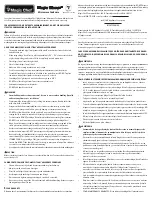
Connections on the cooktop
3
2
1
ZONE1 INTERF. COM1 ZONE2
Fig. 5.21 Connections on the cooktop
[1]
Control knob connection for the front cooking zone (zone 1)
[2]
Connection for the automatic extraction system
[3]
Control knob connection for the rear cooking zone (zone 2)
Cooking zone connection with 1 control knob
X
X
Connect the connection on the back of the control
knob with one of the connections on the cooktop (zone
1 or zone 2).
Cooking zone connection with 2 control knobs
X
X
Connect the connections on the back of the control
knobs with the connections on the cooktop (zone 1
and zone 2).
Connecting the automatic extraction system
X
X
Connect the cooktop extractor to the connection
provided for the automatic extractor system on the
cooktop.
5.5.6 Establishing the power connection
X
X
Observe all safety and warning information (see the
Safety section).
X
X
Observe all national and regional laws and regulations
as well as the supplementary regulations of the local
utility companies.
INFO
The power connection may only be established
by certified specialists. The specialist
also assumes responsibility for the proper
installation and commissioning.
The power supply line to be used (pre-assembled) must
be at least type H05VV-F or H05VVH2-F (see the Fuse
protection and minimum cross-section table).
Connection
Fuse protection
Minimum
cross-section
1-phase connection
1 x 16 A
1.5 mm
2
Tab. 5.4 Fuse protection and minimum cross-section
Q
Q
If the connection cable has been damaged, it must
be replaced. This may only be done by an authorized
member of the After Sales Service team.
X
X
Switch off the main switch/automatic circuit breaker
before connecting the cooktop.
X
X
Secure the main switch/automatic circuit breaker
against being switched back on without permission.
X
X
Make sure the power to the appliance is disconnected.
X
X
Only connect the cooktop using a permanent
connection to a power supply cable.
1
L1
2
N
PE
220 - 240 V~
Fig. 5.22 Connection diagram 1-phase
X
X
Check that installation has been done correctly.
X
X
Switch on the main switch/automatic circuit breaker.
X
X
Put the cooktop into operation (see the Operation
section).
X
X
Check that all the functions are working correctly.
5.6 Configuration menu
Once installation is complete, you can configure certain
basic settings for your cooktop, which you can also
change again at any time.
5.6.1 Opening the configuration menu
X
X
Turn the control knob to the 11 o’clock position.
t
appears on the control knob display.
X
X
Tap the control knob’s touch-operated area. The
display switches to
000
.
X
X
Press the touch-operated area again within 3 seconds,
retaining contact with it for 5 seconds.
Q
Q
C
appears on the control knob’s display, an acoustic
signal sounds and the configuration menu opens.
Summary of Contents for PKIW1
Page 33: ...EN 33 Notes www bora com 11 Notes...
Page 34: ...EN 34 Notes www bora com...
Page 35: ......