PMX40 RF Power Meter – INSTRUCTION MANUAL
4-6
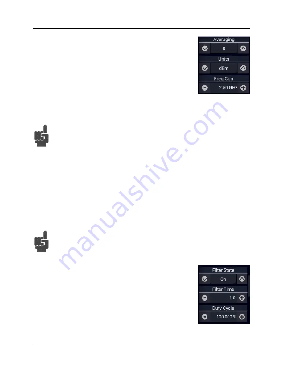
Averaging:
Only available in Pulse and Statistical modes. Set the number
of traces averaged together to form the measurement result on the selected
channel. Averaging can be used to reduce display noise on both the visible
trace, and on marker and automatic pulse measurements. Trace averaging is
a continuous process in which the measurement points from each sweep are
weighted (multiplied) by an appropriate factor and averaged into the existing
trace data points. In this way, the most recent data will always have the
greatest effect on the trace waveform, and older measurements will be
decayed at a rate determined by the averaging setting and trigger rate. This
averaging technique is often referred to as “exponential” averaging because
averaging imposes a first-order Infinite Impulse Response (IIR) exponential filter with a time constant of
"n" where n is the Average (number of averages) setting.
Note
For timebase settings of 200 ns/div and faster, the RTP Series sensors acquire samples
using a technique called equivalent time or random interleaved sampling (RIS). In this
mode, not every pixel on the trace gets updated on each sweep, and the total number
of sweeps needed to satisfy the average setting will be increased by the sample
interleave ratio of that particular timebase. At all times the average trace is the average
of all samples for each pixel, and the min/max are the lowest and highest of that same
block of samples for each pixel.
Units:
Select the channel units. The trace may be shown in units of dBm, Watts, or Volts. The
Units selection determines the range of the scale values and also affects displayed text and
measurement values.
Freq. Corr:
Sets measurement frequency for the RF signal that is applied to the sensor for the
current measurement. The appropriate frequency calibration factor from the sensor’s calibration table
will be interpolated and applied automatically. Application of this calibration factor compensates for
the effect of variations in the flatness of the sensor’s frequency response.
Note
The power sensor has no way to determine the carrier frequency of the applied signal,
so the user must always enter the frequency.
Filter State:
Available in Continuous mode only. Set the current value of
the integration filter on the selected channel. The filter can be set to Off, On,
or Auto. Off, provides no filtering, and can be used at high signal levels when
absolute minimum settling time is required. On, allows a user-specified
integration time to be entered for use. Auto, uses a variable amount of
filtering, which is set automatically by the power meter based on the current
signal level to a value that gives a good compromise between measurement
noise and settling time at most levels.


