


Voorhout • Groningen • Weert • Hoogerheide
T
+31(0)88 7865800
I
elsto.eu
Relay output X10
X10
Inverter error message
1)
Control terminal X210A
X210A.1 DC 20 V output (I
max
=180 mA)
or DC 24 V ±10% input for
external power supply
X210A.2 GND 20 V/ GND 24 V (ext.)
X210A.3 Digital Input
STOA
(first shut-down path)
safety rele-
vant
X210A.4 Digital inputs
1)
X210A.5
X210A.6
X210A.7
Control terminal X210B
X210B.1
Digital Input
1)
X210B.2
Digital Input
STOB
(second shut-down
path)
safety rele-
vant
X210B.3
Digital output
1)
X210B.4
Multifunction output
1)
(voltage sig-
nal, proportional act. frequency,
factory settings)
X210B.5
Supply Voltage DC 10 V for refer-
ence value potentiometer, (I
max
=4
mA)
X210B.6
Multifunction input
1)
(reference
speed 0 … +10 V, factory settings)
X210B.7
Ground 10 V
1)
Control terminals are freely configurable.
11/13
ACU
Winding Drive
21
4 Applications
This chapter describes typical examples of winder applications. The function blocks used are described
in Chapter 5 “Function blocks”.
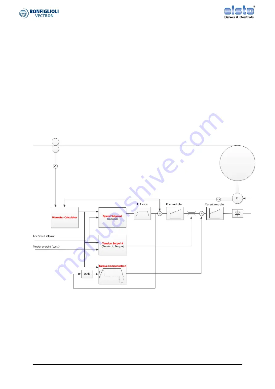
4.1
Example: Indirect tension control
The tension of a web is to be maintained at a fairly constant value. Tension-feedback which might be
used for direct control is not available.
•
The function block “Speed Setpoint” converts the Line Setpoint into a Reference Frequency such
that the winder drive wants to wind 5-10% faster than necessary at all times.
•
The function block “Tension Setpoint” limits the torque to a value which will be just sufficient for
developing the required tension at the current diameter.
•
The function block “Compensation Calculator” (Torque Compensation) calculates the torque addi-
tionally required for turning the winder and acceleration and adds it to the torque supplied by
function module “Tension Setpoint”.
22
ACU
Winding Drive
11/13