background image

4

2

Updating  Firmware

When you select 

Firmware Update

 from the appliance’s web UI, the

Firmware Update page appears. From this page you can determine

which Nyquist version the appliance is using and if an update is

required. You can also use this page to restore factory settings and to

reboot the appliance.

Help

Accesses the appliance’s online help.

Manual

Displays the Nyquist Matrix Mixer Pre-Amp 

Configuration Manual.

Logout

Logs out of the appliance’s dashboard.

Table 2, Appliance Dashboard Buttons

Note: 

A Nyquist appliance connected to the Nyquist network 

receives a configuration file from the Nyquist server that includes 

the latest firmware available from the server. If the firmware is later 

than the one installed on the appliance, an automatic firmware 

update occurs unless the 

Firmware

 parameter for the station is left 

blank. Refer to the 

Nyquist System Administrator Manual

 for more 

information.

Summary of Contents for NQ-PA120

Page 1: ...Public Address Mixer Amplifiers Configuration Manual NQ PA120 NQ PA240 NQ PA600 2019 Bogen Communications Inc All rights reserved 740 00122A 191028 ...

Page 2: ......

Page 3: ...l Level 16 6 2 Signal LED Clip LED and VU Meter 16 6 3 Muting a Channel 16 6 4 Adjusting Volume Levels 16 6 5 Selecting Input Type Mic Gain and Phantom Power 17 6 6 Adjusting Compression Settings 17 6 7 Ducker 19 6 8 Adjusting the Graphic Equalizer 21 6 9 Setting High Low Pass Parameters 23 6 10 Adjusting the Limiter 26 6 11 Adjusting Noise Gate Settings 27 6 12 Adjusting Parametric Equalizer Sett...

Page 4: ...ii ...

Page 5: ...e with Channel Drop Down Menu 13 Figure 8 DSP Output Options 15 Figure 9 Compressor Settings 18 Figure 10 Ducker Parameters 20 Figure 11 Graphic EQ Settings 21 Figure 12 High Low Pass Parameters 23 Figure 13 Limiter Settings 26 Figure 14 Noise Gate Settings 27 Figure 15 Parametric Equalizer Settings 29 Figure 16 Router Settings 31 Figure 17 Settings Parameters 32 Figure 18 Signal Present Parameter...

Page 6: ...iv ...

Page 7: ... 3 Network Settings 7 Table 4 Configuration Settings 9 Table 5 Logs 12 Table 6 DSP Page 14 Table 7 Compressor Settings 18 Table 8 Ducker Parameters 21 Table 9 High Pass Low Pass Parameters 24 Table 10 Limiter Settings 26 Table 11 Noise Gate Settings 28 Table 12 Signal Present Parameters 34 Table 13 Status 35 ...

Page 8: ...vi ...

Page 9: ...the appliance returns to the factory default configuration settings Returning to the default configuration settings does not change the appliance s firmware The following sections describe the process for manual configuration For information about using Nyquist s automatic configuration pro cess refer to the appropriate Nyquist System Administrator Man ual To access the appliance s UI Step 1 Acces...

Page 10: ...e Login page enter username and password and then select Login The default username is admin the default password is bogen The dashboard for the selected appliance appears Figure 1 Nyquist Appliance Login Figure 2 Appliance Dashboard ...

Page 11: ...ons Dashboard Refreshes the dashboard Configuration Set tings Accesses the Configuration Settings page where you can either manually set various options such as the SIP Username or select to receive configuration settings from the server Network Settings Accesses the Network Settings page where you can view and set network settings such as the static IP address Firmware Update Accesses the Firmwar...

Page 12: ...nual Displays the Nyquist Matrix Mixer Pre Amp Configuration Manual Logout Logs out of the appliance s dashboard Table 2 Appliance Dashboard Buttons Note A Nyquist appliance connected to the Nyquist network receives a configuration file from the Nyquist server that includes the latest firmware available from the server If the firmware is later than the one installed on the appliance an automatic f...

Page 13: ... file that you want to upload You can navigate to the file s location After you select the file select Upload If Nyquist discovers a new firm ware version the Firmware Update page displays an Update Firmware button Select this button if you want to update the appliance s firmware to the new version Step 3 If you want to return your appliance to its original state undoing firmware updates select Re...

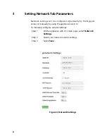
Page 14: ...dynamically by the Nyquist server or manually by using the appliance s web UI To manually configure network settings Step 1 On the appliance web UI s main page select Network Settings Step 2 Select your desired network settings Step 3 Select Save Figure 4 Network Settings ...

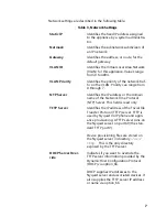
Page 15: ...address or the domain name of the Network Time Protocol NTP Server This field is read only TFTP Server Identifies the IP address of the Trivial File Transfer Protocol TFTP server TFTP is used by Nyquist VoIP phone and appli ance provisioning A TFTP server runs on the Nyquist server on port 69 the stan dard TFTP port Device provisioning files are stored on the Nyquist server in directory srv tftp T...

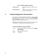
Page 16: ...I To manually configure your Nyquist appliance Step 1 On the appliance Web UI s main page select Configu ration Settings Step 2 Select your desired settings Step 3 Select Save DHCP Enabled Indicates if the device is enabled to use DHCP Reboot Appliance Allows you to save the network options and reboot the appliance Table 3 Network Settings Continued Note Manual configuration will be overwritten by...

Page 17: ...ure 5 Appliance Configuration Settings Table 4 Configuration Settings Web Username Provide a web username for this appli ance Web Password Provide a web password for logging into the appliance Web Confirm Pass word Re enter the password used to log into the appliance ...

Page 18: ...port number and volume used for all calls pages Audio Distribution Identifies the IP address port number and volume used for audio distribution Multicast Identifies the multicast IP address for a zone that the speaker is included in If a speaker is added to multiple zones the multicast IP address for each zone appears Port Number Identifies the port number of the appli ance Port Type Identifies th...

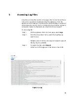
Page 19: ... your PC Mac or Android device and then copied to removable media or attached to an email to technical support To view a log file Step 1 On the appliance Web UI s main page select Logs Step 2 From the drop down menu select the log that you want to view Multiple versions of the same log and zipped copies of the log may be available Step 3 To export the file select Export A link to a txt file appear...

Page 20: ...ains information logged by the various back ground daemons that run on the system debug Contains errors and debug information dmesg Contains kernel ring buffer information When the sys tem boots up the screen displays information about the hardware devices that the kernel detects during the boot process These messages are available in the ker nel ring buffer and whenever a new message comes the ol...

Page 21: ...occur when the server is run ning and server start and stop records user log Contains information about all user level logs wtmp Contains historical record of users logins at which ter minals logouts system events and current status of the system and system boot time wvdialconf log Contains basic information about the modem port speed init string and Internet Service Provider ISP Table 5 Logs Cont...

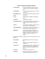
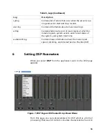
Page 22: ...menu of other parameters Some of these parameters affect all channels in which case a channel number does not appear on the top of the graphic If a parameter affects only the selected channel a channel number appears on the selected parameter graphic DSP parameters and the Mute and Level buttons are described in the following table Table 6 DSP Page Mute Silences the audio for the selected channel ...

Page 23: ...ble for the output Parametric EQ Uses a center primary frequency to all tailor ing of the frequency content of an audio sig nal Router Routes audio to different devices Settings Allows you to provide names and colors for the input and output channels Status Provides real time status of the selected channel Table 6 DSP Page Continued Figure 8 DSP Output Options ...

Page 24: ...ing to deliver an output voltage or cur rent beyond its maximum capability Clipping will distort the sound and can damage a speaker The VU meter not only illuminates green yellow or red depending on the signal level but also has a scale ranging from 60 to 0 to help you indicate the actual signal level 6 3 Muting a Channel You can mute a channel to cut off an audio signal and stop the pro duction o...

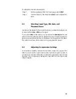
Page 25: ...as the input you can adjust the Mic Gain dial and select if the microphone will use phantom power Phantom power is electrical power that is sent to a condenser mic through its mic cable The cable must have XLR connectors to pass phantom power 6 6 Adjusting Compression Settings A compressor slightly reduces the dynamic range of a signal This effect is perceived to quiet loud sounds and boost quiet ...

Page 26: ... page 18 Step 5 Select Enable to apply the settings to the selected channel Figure 9 Compressor Settings Note If you want to return to the factory settings select the Reset icon that appears in the right corner Table 7 Compressor Settings Threshold Sets the threshold level which is the point where the signal activates the compressor circuit The range is 135 to 21 dB Attack Sets how fast the compre...

Page 27: ... how long the compressor is on after the signal has fallen below the threshold The range is 1 to 500 ms Decay Sets the rate of turn off of the compressor after the signal is below the threshold he range is 0 to 2000 ms Knee Sets how the compressor reacts to signals once the threshold is reached Increasing the knee level decreases the obvious tran sition from the uncompressed to the com pressed sou...

Page 28: ...button for the channel or select the Menu button for the Output Step 3 From the drop down menu select Ducker Step 4 Make desired adjustments using the controls described in the following table Figure 10 Ducker Parameters Note If you want to return to the factory settings select the Reset icon that appears in the right corner ...

Page 29: ...ters Threshold Sets the threshold level or how loud the sig nal has to be before ducking is enabled The range is 135 to 20 dB Hold Sets how long the master continues to duck the signal after the signal is below the threshold The range is 1 to 500ms Master Select the channel that serves as the master or unducked channel The audio on this channel has priority audio for all other chan nels is ducked ...

Page 30: ...range from 25 Hz to 20 000 20k Hz By default each knob is set at 0 dB which means that no frequencies are being boosted or cut Step 4 Adjust frequencies as desired ensuring the Enable LEDs are green for the selected frequencies Note For the best results frequencies should be cut only Boost ing frequencies to compensate for room dimensions or speaker response deficiencies usually results in a loss ...

Page 31: ...own menu option To adjust the high low pass parameters for a channel Step 1 On the appliance Web UI s main page select DSP Step 2 Select the Menu button for the channel Step 3 From the drop down menu select High Low Pass Step 4 Set the parameters described in the following table Figure 12 High Low Pass Parameters Note If you want to return to the factory settings select the Reset icon that appears...

Page 32: ...y You can adjust the frequencies by moving the knob or by dou ble clicking the knob and typing the fre quency When typing the frequency only numeric values from 20 Hz to 20 000 Hz can be entered The high pass filter attenuates content below this frequency and lets frequencies above this cutoff frequency to pass through the fil ter Type Available filter types are Linkwitz Riley 12 24 and 36 dB per ...

Page 33: ...larly effective when hand held microphones are used Frequency Set the cutoff frequency You can adjust the frequencies by moving the knob or by dou ble clicking the knob and typing the fre quency When typing the frequency only numeric values from 20 to 20 000 can be entered The low pass filter attenuates content above this frequency and lets frequencies below this cutoff level to pass through the f...

Page 34: ...tep 1 On the appliance Web UI s main page select DSP Step 2 Select the Menu button for the channel or select the Menu button for the Output Step 3 From the drop down menu select Limiter Step 4 Adjust the following settings as needed Figure 13 Limiter Settings Note If you want to return to the factory settings select the Reset icon that appears in the right corner Table 10 Limiter Settings Threshol...

Page 35: ...s for a channel Step 1 On the appliance Web UI s main page select DSP Step 2 Select the Menu button for the channel Decay Sets the rate for turn off of the limiter after the signal is below the threshold Decay range is 5 to 2300 milliseconds RMSTC Sets how fast the limiter reacts to the above threshold signal RMSTC range is 50 to 10000 Figure 14 Noise Gate Settings Table 10 Limiter Settings Contin...

Page 36: ...l must be below for the noise gate to close pre vent the sound from getting through Threshold range is 135 to 21 db Attack Adjusts how long it takes for the gate to open once the signal falls below the thresh old Attack range is 1 to 500 ms Hold Defines the length of time the gate will stay fully open after the signal falls below the threshold Hold range is 1 to 500 ms Decay Sets the rate for turn...

Page 37: ...s main page select DSP Step 2 Select the Menu button for the channel Step 3 From the drop down menu select Parametric EQ Step 4 Adjust frequencies as desired ensuring the Enable LEDs are green for each selected frequency You can adjust the frequencies by moving the Freq knob or by double clicking the knob and typing the frequency When typing the frequency only numeric values from 20 to 20 000 can ...

Page 38: ...se the Gain knob or double click the knob and type the gain to either boost turn up_ or cut turn down Gain knobs can be moved between 12 or 12 dB By default each knob is set at 0 dB which means that no frequencies are being boosted or cut Step 7 Select Save Settings to Server 6 13 Adjusting Router Settings Router settings allow you to manipulate signal gain settings in the DSP The Router is also u...

Page 39: ...tput and cross gain settings as desired Step 5 To route a signal to a specific output select the Input s Enable button so that it changes from gray to green This signal can be sent to Network 1 2 3 or 4 or to the Analog for the Line Output or Speaker Out or to all Network outputs are signals that are sent over the Figure 16 Router Settings Note If you want to return to the factory settings select ...

Page 40: ... Channels 1 to 4 can be mixed to each out put as desired Multiple input signals can be mixed to multiple outputs or to a single output Likewise outputs are enabled by selecting the Enable button for the selected outputs turning the button from gray to green 6 14 Settings You can set select names and colors for each of the input and output channels Figure 17 Settings Parameters ...

Page 41: ...want to dis play for the channel Step 5 For each channel select a color that will be used to highlight the channel Step 6 Select Save 6 15 Signal Present You can set parameters for when a channel accepts a signal You can set specific parameters for each input channel and for the output channel Note If you want to return to the factory settings select the Reset icon that appears in the right corner...

Page 42: ...t Signal Present Step 4 Adjust the following settings as needed Note If you want to return to the factory settings select the Reset icon that appears in the right corner Table 12 Signal Present Parameters Threshold Sets the threshold level or at what level the Signal LED is illuminated Hold Sets the number of milliseconds that the sig nal light stays on after the signal is no longer present ...

Page 43: ... amplifier Step 1 On the appliance Web UI s main page select DSP Step 2 Select the Menu button for the channel Step 3 From the drop down menu select Status The view only information that appears is described in the following table Figure 19 Status Table 13 Status Thermal Protect Appears red if the equipment has become too hot and has placed itself into protection mode Otherwise the LED is green ...

Page 44: ...mit Appears red if the output signal is being clipped or distorted Otherwise the LED is green Temperature Provides the real time temperature of the appliance in both Celsius and Fahrenheit Table 13 Status Continued ...

Reviews: