background image


SX-16 Nightsun

®

 Searchlight System 


Maintenance Manual 

Document 031734-1/Revision A  

031734-1 Revision B 


January 27, 2014


4.9.3 

Preparation for Painting 

After removing any corrosion: 


Sand the area lightly with medium grit sandpaper (120 or 220 grit), then wipe the area clean 
of sanding residue. 


If the primer or other paint requires any further surface preparation, follow the manufacturer’s 
instructions. 


If entire arm is going to be repainted, remove the Gearboxes and other attachment hardware 
from the arm. 


Mask the identification tag to preserve its information. 

4.9.4 

Priming and Painting 

After sanding and priming the area as required, follow the paint manufacturer’s instructions. Use an 
aircraft rated exterior primer and flat black or semi-gloss black paint. 


For aluminum Gimbals, use a primer rated for aluminum. 


For steel Gimbals, use a primer rated for steel. 

4.9.5 

Return Gimbal to Service 

Follow the instructions to reassemble the Gimbal and Searchlight on the aircraft. 


Replace the Gimbal arm on the aircraft (

Gimbal Installation Procedure

  section of this 

manual), and verify that the motor service loops and cable ties  are in place (

Service Loops


section of this manual). 


Replace the Searchlight. 


Reattach all safety cables to the Gimbal assembly, Searchlight, and aircraft. 


Perform a full system functional check. 

4.10  Replacement of the Gimbal Arms 

Replacement of the Gimbal arm is a relatively simple procedure. It does not require special tools or 
training. Nonetheless, a certified aircraft mechanic who is familiar with the practices, processes, and 
visual inspection techniques to be used on flight hardware should conduct the replacement. The 
aircraft mechanic should verify that all hardware is in sound, flight-worthy condition upon completion 
of this procedure. 

4.10.1  Identification Tag 

When Gimbal arms are replaced, a new identification nameplate will be provided by Spectrolab. This 
ensures the traceability of the new hardware. When new Gimbal arms  are ordered,  make sure to 
enclose a notice with the old serial number and Gimbal part number. 

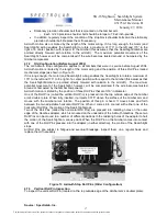
4.11  Removal Procedure for Gimbal with current Azimuth Stop Configuration (After August 

2004) 

To remove the old Gimbal arm: 


Remove the Searchlight from the existing Gimbal. 


Prepare to remove the existing Gimbal arm: 

o


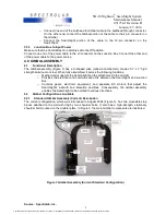
Observe the orientation of the Azimuth  (upper)  Gearbox  to aircraft mounting. Make 
pencil marks so that you can install the Gearbox to the same position relative to the 
new Gimbal arm when reinstalled. 

o


Note the orientation of the drive motor with respect to the Gimbal arm so that it can 
be installed in the same position with the new Gimbal arm. 
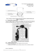
o


Observe the routing of the cables, service loops, and the position of the cable ties so 
that you can replicate them later. 

o


Remove any cable ties that hold the Gimbal motor wires in place, and again take 
note of their location. 

o


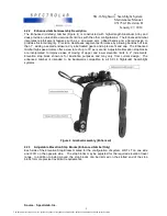
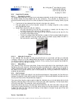
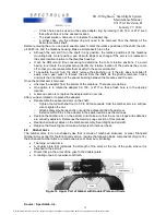
Examine the two moveable stop blocks attached to the Azimuth  ring, and examine 
the stationary shoulder bolt that is attached to the Gimbal arm. 
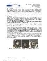
o


Make sure that there is no more than 2° of backlash on the elevation Gearbox and on 
the  Azimuth  Gearbox. If either Gearbox  has more than 2° of backlash, adjust or 
repair the Gearbox before installing them on the new Gimbal arm. 


Source:  Spectrolab, Inc. 

22


The document reference is online, please check the correspondence between the online documentation and the printed version.

Summary of Contents for SPECTROLAB SX-16 Nightsun

Page 1: ...separate manual provides information about operation 1 3 Read Obey and Keep Instructions To ensure the safety of people and equipment it is important to read and obey all instructions and safety warni...

Page 2: ...a voltmeter to verify that voltage in the Junction Box s large Capacitor has discharged from its 125 to 150 VDC level before touching its terminals o Similarly use a voltmeter to verify that the start...

Page 3: ...nt should be resistant to 500 F 260 C Barbecue or automotive exhaust manifold paint works well The target should be well supported by a stand that is non flammable During use it will become very hot a...

Page 4: ...install the Searchlight in locations that allow the light beam to be aimed at nearby temperature sensitive surfaces without taking appropriate steps to mitigate possible damage The light absorbed by d...

Page 5: ...dicate a hazardous situation that could result in minor or moderate injury if not avoided A caution message has the following appearance 2 3 Notice Messages Notice messages are also used in this manua...

Page 6: ...ed from its Gimbal mounting the safety cables will prevent the Gimbal or Searchlight from potentially falling free of the aircraft Before installing the Searchlight test the installation location Duri...

Page 7: ...connections Junction Box to the Control Box Junction Box to the Gimbal assembly and Searchlight Junction Box to the input power 3 5 1 Junction Box to Control Box In the compartment where the Control B...

Page 8: ...embled it serves the following functions o Mechanically supports the Searchlight and the attachment to the aircraft o Provides the electrical and communication link between the Searchlight and Junctio...

Page 9: ...cond Adjustable Elevation stop blocks are incorporated to improve ease of moving of upper and lower elevation limits in 2 increments Elevation stop block shown is for illustration purposes and may var...

Page 10: ...es on the bottom of the Gearbox It also has a fixed vertical Roll Pin mounted on top of the doubler plate In Figure 6 the main Gimbal components are illustrated Figure 6 Gimbal Assembly Older Standard...

Page 11: ...210 Enhanced Uni body 230 Enhanced Uni body with SpectroLink 022955 Series Steel 21 Standard 121 Standard High Speed 130 SpectroLink 140 IFCO SpectroLink 4 3 3 Elevation Attachment and Movement In ad...

Page 12: ...hs or 300 flight hours or 100 operation hours Use the following inspection procedures Daily o Verify that both Wing Bolts are in place and that the lanyards are connected to the angle clips on the Gim...

Page 13: ...rs or switches will have a second separate connector If not you may have to replace the standard 4 pin connector with one that has more pins 4 5 2 3 Motor Wires The condition of all motor wires is imp...

Page 14: ...archlight systems include electronically programmable stops as part of ancillary equipment such as a moving camera that has been specially installed Adjustment of these programmable stops is addressed...

Page 15: ...of the elevation stop since the replacement will be installed in the same orientation Remove the four 4 torque set flat head screws P N NAS1102E08 5P 8 32 x 5 16 LG attaching the existing Elevation st...

Page 16: ...ced in August 2004 It consists of two adjustable stop blocks Each stop block is attached to the Azimuth Adapter ring by two shoulder bolts Figure 12 The stop blocks limit movement of the Gimbal when t...

Page 17: ...o the aircraft The maximum potential movement of the Searchlight however will be compromised if the wire becomes twisted around or hampered by the Gimbal components Azimuth motion is limited by the po...

Page 18: ...arged If the hole has been enlarged in this way replace the Gimbal arm There is no repair procedure for an enlarged Roll Pin hole o If the new pin fits snug reassemble the spacer and arm on the shaft...

Page 19: ...ter from the bottom of the Gearbox There are two options One option is to rotate the adapter 90 180 or 270 so that a fresh hole is in the desired location A second option is to replace the adapter wit...

Page 20: ...bal arms pay particular attention to the area of the doubler plate and the rivets Inspect for signs of cracks corrosion or chipped or peeling paint o If any cracks or any loose or broken rivets are fo...

Page 21: ...propriate for use on 7075 aluminum alloy Follow the manufacturer s instructions Make sure to remove all residues before painting For steel Gimbals reference Gimbal Part Numbers Available by Descriptio...

Page 22: ...to be used on flight hardware should conduct the replacement The aircraft mechanic should verify that all hardware is in sound flight worthy condition upon completion of this procedure 4 10 1 Identif...

Page 23: ...imbal arm when it is reinstalled o Note the orientation of the drive motor with respect to the Gimbal arm so that it can be installed in the same position with the new Gimbal arm o Observe the routing...

Page 24: ...the Azimuth clutch to slip Drive the arms through their entire range of motion in each direction until they hit both of the stop blocks o Verify that the wires do not pull at the connector or where t...

Page 25: ...he arms through their entire range of motion in each direction until they hit both of the stop Roll Pins o Verify that the wires do not pull at the connector or where they enter the motor boots Remove...

Page 26: ...vice will then stop the motor electronically just before it hits the mechanical stops It is important to be aware of this behavior so that you can differentiate this kind of motor stopping from a clut...

Reviews: