SX-16 Nightsun
®
Searchlight System
Maintenance Manual
Document 031734-1/Revision A
031734-1 Revision B
January 27, 2014
o
A fresh hole can be used on the same adapter ring by rotating it 90, 180, or 270° such
that a fresh hole is in the desired location.
o
The ideal solution, however, is to replace the adapter ring.
o
In either case, you the adapter ring will need to be removed from the bottom of the
Azimuth Gearbox shaft.
Before removing the arm, use a permanent marker to mark the relative positions of the shaft, the arm,
all Roll Pins, and the Gearbox housing. Make a simple sketch to do this.
•
Although the arm will fit on the shaft in any position, the relative positions of the Gearbox
mounting bolts, motor position, and Azimuth stops may change if the arm is not replaced in
the same location relative to the Gearbox housing.
•
It can be difficult and time consuming to determine the correct relative positions. To avoid
having to recreate the original setup, identify the relative location of the parts as they come
off so that you can reassemble them exactly in the same orientation.
•
To separate the arm from the shaft, remove the attaching nut. If the arm does not slide off
easily, use a gear puller to remove the arm from the shaft. As the shaft is removed, notice
and mark the orientation of the spacer bushing between the Gearbox and the arm.
Once the Gimbal arm is removed:
•
Unscrew the adapter from the bottom of the Gearbox. There are two options:
•
One option is to rotate the adapter 90, 180, or 270° so that a fresh hole is in the desired
location.
•
A second option is to replace the adapter with a new one.
After you have rotated or replaced the adapter:
•
Reassemble the spacer and arm on the shaft.
o
Tighten the Azimuth shaft nut to 50 to 60 foot-pounds. Hold the Gimbal arm in a soft jaw
vise to tighten the nut.
o
Attach safety wire between the nut and the adjacent drilled head screw.
o
Install new Roll Pins in the adapter in the same locations as the old ones.
•
Replace the Gimbal arm on the aircraft, and make sure that the service loops and cable ties
are correctly adjusted. Reference the
Service Loops
section of this manual
•
Reattach all safety cables on the Gimbal assembly, Searchlight, and aircraft.
•
Replace the Searchlight and make a full system functional check.
4.8
Gimbal Arms
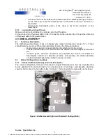
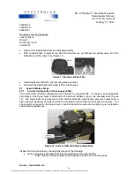
The Gimbal Arms form a U-shaped yoke that is made of machined aluminum or steel. Standard
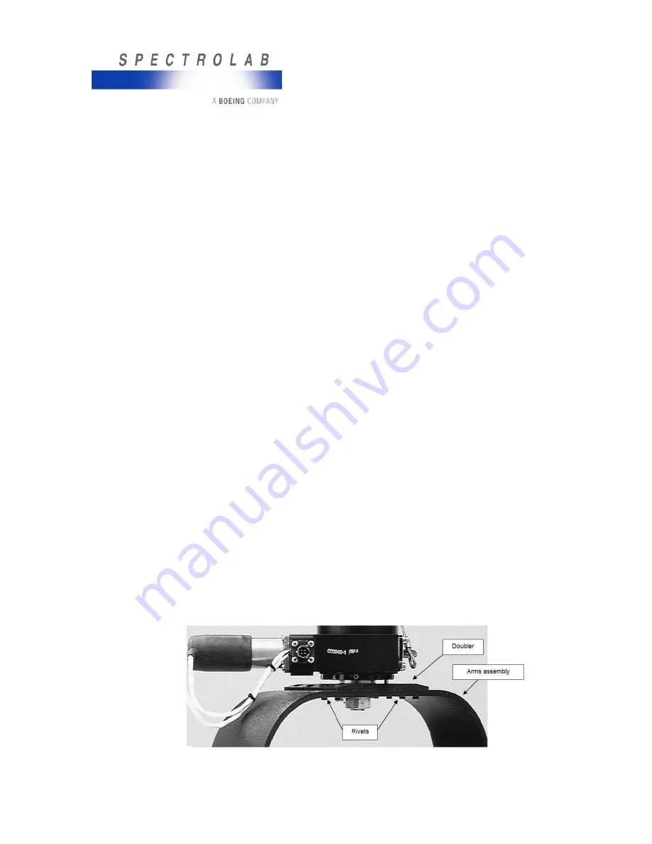
Gimbal Arms except for the Enhanced version, include the following basic components (Figure 14),
the Enhanced Gimbal Arms are made one piece of Aluminum (Unibody):
•
The large, curved arms.
•
A doubler plate that increases the strength of the arms at the top of the yoke, where it is
attached to the aircraft.
•
Rivets that join the arms of the yoke to the doubler plate.
•
A coating of paint or powder-coat finish.
Figure 14 Upper Part of Gimbal with Doubler Plate and Rivets
Source: Spectrolab, Inc.
19
The document reference is online, please check the correspondence between the online documentation and the printed version.

