background image

tighten the counter bolts (3). On 
the right side, the tool should be 
pulled downwards and on the 
left side upwards to tighten. 

5: The belt should be tightened 
to approximately 125 kg/229 Hz. 
To measure this, a special device 
can be bought at your local 
BODY BIKE Distributor.

6: Tighten the counter bolt (2) 
on both sides of the cycle again.

7: And tighten the bolt(1) again 
on both sides of the cycle. 

8: Close the cycle by fastening 
the two hatches again.

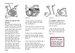
REMOVAL OF SIDE
COVERS

The side covers can be re-
moved e.g. if the belt needs to 
be changed.

1: Dismount the right pedal 
arm with an 8mm Allen 
wrench. 

2: Loosen all the screws hold-
ing the side cover with a 3 
and 4 mm Allen wrench and 
remove them.

3: Dismount the top nut and 
washer on the bottom frame 
on the right side of the cycle 
both in front and back with a 
13 mm wrench.

4: Screw the bolts down in 
order for the side covers to 
slide past them.

5: Remove the side cover.

Please note:

The belt should be 
equally tightened 
on both sides.

POLY-V BELT

If the belt does not catch hold 
of the flywheel, it is time for it 
to be tightened.

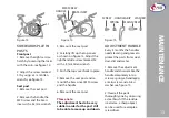
1: Remove the service hatch 
on both sides of the cycle by 
loosening the three locks with 
a coin, see figure 10.

2: Loosen the bolts (1) on both 
sides of the cycle with a 19 
mm wrench, see figure 20.

3: Loosen the nuts (2) on the 
counter bolt on both sides of 
the cycle, see figure 20.

4: Use a 10 mm wrench to 

(1)

(2)

(3)

Figure 20

Summary of Contents for Classic Supreme

Page 1: ...Instructions for your BODY BIKE Indoor Cycle BODY BIKE I N DOOR CYCLE BODY BIKE Classic Supreme ...

Page 2: ...MENT REQUIRED Unpacking Drill bit Drill Bottom Frame 13 mm wrench Saddle 14 mm wrench Pedals 15mm pedal wrench Grease Cleaning Tissue paper or cloth Spray bottle with water Soap only washing up liquid Vaseline oil Lubrication A coin Oil Special sponge tool or cloth Post Cleaning Cloth Vaseline oil Sidewards play in posts A coin 3mm Allen wrench 32mm wrench Adjustment Handle 5mm Allen Wrench Screwd...

Page 3: ...nd clear instructions on how to maintain the cycle Over time it will be necessary to replace worn out parts You will find a detailed description of all BODY BIKE s spare parts on our website www body bike com When ordering spare parts from the local BODY BIKE distributor please refer to the item number P N no in order to make sure you will receive the correct spare part We recommend that you order ...

Page 4: ...cle Length Width Height Assembled size 105cm 60cm 100cm Packed size 5 cycles 120cm 80cm 114cm Weight Assembled 65 kilogram Packed weight 5 cycles 350 kg Patent held for Crank system Maximum user weight 150 kg Please note that the max pedal load may be lower Materials Cast iron Stainless steel Plastic ABS covers High quality bearings Frame Robot welded powder coated and hardened ...

Page 5: ...ered by a warranty There is currently no warranty applying to the pedals GENERAL INFORMATION Wipe off the cycle after EVERY use ALWAYS loosen all handles and release tension after use The rubber feet should always be adjusted to ensure that the cycle is in level Every other year the rubber feet should be replaced as the rubber hardens and becomes unable to absorb the impact Pedals should be change...

Page 6: ...Unpacking 7 Bottom frame 8 Handlebar 9 Bottle holder 9 Saddle 9 Pedals 9 ASSEMBLY ...

Page 7: ...g the top of the box 2 Remove all the unmounted parts 3 Flatten the box on the floor next to the pallet 4 Loosen the two screws mounting the first cycle to the pallet 5 Lift the cycle off the pallet and place it on the flattened box to spare your floor from getting marks ...

Page 8: ... the bottom frames see figure1 Ensure that the holes in the frame match the holes in the bottom frames 3 Put on the spring lock washer and the cap nut and tighten by using a 13 mm wrench see figure 2 Please note Do not overtighten the nuts They should only be hand tight 4 Unscrew the rubber feet a little Place the cycle in the correct position Turn them up and down until the cycle stands properly an...

Page 9: ...e pedals are marked with R for Right and L for Left side the pedals should always be screwed on in the direction of the handlebar see figure 8 make sure that the hole in the pedal arm is greased when mounting the pedal start mounting the pedal by hand as tools will tighten the pedal at a wrong angle 3 After tightening by hand use a 15mm pedal wrench to tighten the pedal completely 45Nm BOTTLE HOLDE...

Page 10: ...ary 12 Cleaning the posts Every other week 12 Sidewards play in posts When necessary 13 Adjustment handles Min every 3 months 13 Replacing the brake pad When necessary 14 Poly V belt When necessary 16 Removal of side covers When necessary 16 MAINTENANCE ...

Page 11: ...bar and saddle NEVER use alcohol or chemicals To make the cycle look its best use a cloth with a little vaseline oil on all parts except the handlebar and saddle At an annual service check remove the right side cover and make sure that the small hole by the front bottom frame is not blocked and allows water and sweat to exit the frame see figure 9 Also check that the ribs on the poly v belt and pul...

Page 12: ...e posts need cleaning to protect them from sweat etc 1 Pull out the seat post and the front post and wipe them clean with an oily cloth see figure 12 Figure 10 Figure 11 Figure 12 SERVICE HATCH Please note The posts should be cleaned every other week to keep them in good condition 1 Remove the service hatch by loosening the three locks with a coin see figure 10 2 Wet the special sponge tool with oil...

Page 13: ...N POSTS Front post 1 Remove the right service hatch by loosening the locks with the coin see figure 10 2 Adjust the screw marked S1 by using a 3 mm Allen wrench see figure 13 Seat post 1 Remove the seat post 2 Remove the handle the M30 screw and the brass inset with a 32 mm wrench 3 Remount the seat post 4 Carefully lift up the top cover as shown on figure 14 Adjust the righthandside screw marked S2 ...

Page 14: ...he screw furthest away from the brake see figure 17 Figure 16 3 Lubricate the internal parts with grease before reassembling the handle Remember to lubricate inside the handlegrip as well 4 Reassemble the handle by inserting the main screw in the handlegrip 5 The spring is inserted into the top of the handle and fixed in place with the remaining screw 6 Tighten with a 5mm Allen wrench 7 Add grease t...

Page 15: ...amaged so these can be reused see figure 19 6 Place the screws in the new leather pad and mount it by using the same tools 7 Push the brake back in its right position 8 Mount the brake to the frame by using the removed screw and tightening the other screw 9 Clean the flywheel with a cloth and then lubricate see page 12 10 Test the system before closing up by putting slight resistance on the brake an...

Page 16: ...ch 2 Loosen all the screws hold ing the side cover with a 3 and 4 mm Allen wrench and remove them 3 Dismount the top nut and washer on the bottom frame on the right side of the cycle both in front and back with a 13 mm wrench 4 Screw the bolts down in order for the side covers to slide past them 5 Remove the side cover Please note The belt should be equally tightened on both sides POLY V BELT If t...

Page 17: ...ndlebar 8 Height 4 Information general 5 Length 4 Maintenance 11 16 Manufacturer 4 Mounting 7 9 Patent 4 Pedal 9 Poly V belt 14 15 Post front and seat 12 How to lubricate See page 12 How to keep the cycles in good condition It is a good idea to place a board at the exit of the spin ning room displaying all cycle numbers Here people can write possible problems or concerns arisen during the exercise...

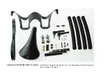
Page 18: ...CLASSIC SUPREME FIRST AID KIT Including a range of spare parts for easy replacement of wearing parts Item number 97200010 ...

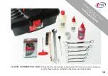
Page 19: ...19 CLASSIC SUPREME TOOL BOX Handy tool box containing a wide range of tools for maintenance purposes e g the three spanners included in the starter set Item number Find spare parts and accessories on our website www body bike com ...

Reviews: