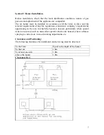

Section 13: Heater Controls
The heater can be used with most Building Management Systems.
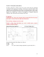
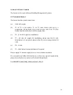
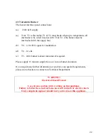
2:1 Turndown Burner:
The heater interface panel connections:
(a).
240v & N supply
(b). T1 & T2 is the enable, T1 & T2 must break when up to a
temperature, all interlocks to be wired in series with T1 & T2. (The
burner must be interlocked with the supply fan).
(c).
T6 - is 10v DC signal for modulation
(d). T7 - 24 volts AC supply for modulating, please note the 24 volts
transformer is in our panel, please advise if you are using external 24
volts.
(e)
T8 - 0 volts
(f)
T5 - 240v burner lockout indication if required.
Please supply 15 minutes supply fan over run on burner shutdown
If you require any further information or you have any special requirements
please do not hesitate to contact our Technical Department.
For ON/OFF Control Only, Omit sections C, D & E
21


