

Section 8: Flue System
The flue system must be made to the following specifications:
a)
Mechanically robust.
b)
Resistant to internal and external corrosion.
c)
Non-combustible and durable under the conditions to which they are to be
subjected.
d)
Stainless steel flue is recommended.
Design
When designing a flue system for the appliance the designer must take into
account the following points.
a)
The flue gases exiting the appliance can be as great as 350 ºc and as low as
70 ºc on modulating burners.
b)
Prevention of condensation within the flue and the management of drainage
from the flue; for example the use of twin wall flue will minimise the
condensation.
c)
Flue must be a type acceptable to current standards.
d)
Facilities should be made for the disconnection of the flue from the heater
to aid servicing and inspection.
e)
This appliance does not require a draught diverter.
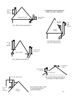
f)
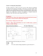
BMM Heaters recommend that a 90º Tee condensate piece is connected
directly onto the heater spigot, from this point the flue must then rise
vertically with no horizontal runs of flue pipe or 90º bends. If there is an
unavoidable obstruction then the use of 45º bends will be permitted.
(Please contact BMM Heaters if more that two 45º bends are used).
g)
The flue should terminate in a freely exposed position and must be situated
as to prevent the products of combustion entering the building via any
opening.
h)
A Flue terminal must be fitted.
i)
The flue installation must be designed to the latest gas regulations and any
local environmental standards.
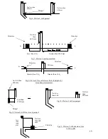
j)
Where a flue passes through a combustible roof, ceiling or floor, the flue
pipe should be surrounded with a metal sleeve, the size of which should be
sufficient to provide a space not less than 25mm between the flue pipe and
the sleeve when positioned.
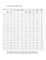
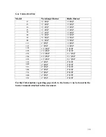
Note! Flue connection sizes can be found in section 4 table 1
11


