BLUM MINIPRESS PRO Operating Instructions Manual Download Page 17

17

BA-102/2EN M54.XXXX


3 - How to operate the machine

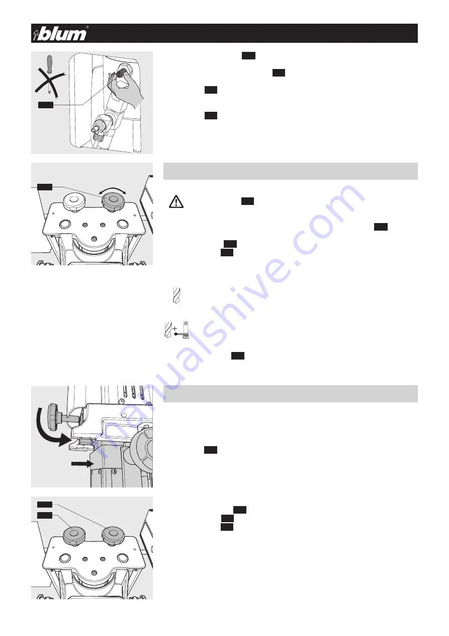
3.5.3) Setting cam brake 

(3.7)


The brake is set by turning the screw 

(3.7)

 on the cylinder.

•  Turn screw 

(3.7)

 to the right:

slows down the drill bit

•  Turn screw 

(3.7)

 to the left:

speeds up the drill bit

3.6.1) “Drilling” and/or “Drilling and inserting fittings” mode switch 

(3.6)


•  Press feed switch 

(2.2)


•  Set mode switch 

(3.6)

 to the desired setting

3.7.1) Assembly of furniture hinges, furniture connectors, METABOX and  

TANDEMBOX front fixing brackets

•  Insert the gear box (see point 3.1.1)

•  Insert ruler 

(8.2)


•  Set work top

•  Set hold down clamp 

(3.3)

 (see point 3.3.1)

•  Set drilling depth 

(3.4)

 (see point 3.4.1)

•  Set mode switch 

(3.6)

 to “Drilling and insertion”

(see point 3.6.1)

3.6 - Setting operating mode

Pos. A - Drilling

The return stroke of the assembly machine is limited.

Pos. B - Drilling and/or inserting fittings

The vertical drilling unit uses a full stroke.

3.7 - Drilling and inserting fittings

Important:

Particular care must be taken when working on sections that jut out 

over the work top. Use extensions.

ATTENTION:

Set main switch 

(2.1)

 to Pos. 0

•  Release feed switch 

(2.2)


3.6

  !

3.7

3.6

3.4

Summary of Contents for MINIPRESS PRO

Page 1: ...2EN M54 XXXX Please keep a copy of the operating instructions The operating instructions contain the EC Declaration of Conformity which must be produced for authorities upon request MINIPRESS PRO EN HO 051140 ...

Page 2: ... Do not remove replace immediately with original parts if damaged 1 4 2 1 2 4 1 2 2 2 2 3 1 10 3 1 3 3 1 1 3 6 1 9 3 4 5 1 3 3 1 5 3 2 1 7 1 1 1 4 5 1 3 4 3 6 3 2 3 5 3 7 1 8 1 7 1 3 3 3 3 2 1 4 3 4 3 6 2 1 2 4 1 8 1 2 1 3 2 2 2 3 3 3 3 3 5 1 1 5 1 7 1 1 1 0 ...

Page 3: ...otor rotation 12 1 4 Dust extraction 13 1 4 1 Connecting extraction system to the assembly machine 13 1 4 2 Attaching the extraction system with the controller 13 2 Description of operator panel 14 2 1 Description of operator panel 14 2 1 1 Designation of operating elements 14 2 1 2 Feed switch 3 2 14 2 1 3 Hold down clamp switch 3 3 14 3 How to operate the machine 15 3 1 Vertical drilling unit 15...

Page 4: ...lling and insertion head MZK 2110 24 7 2 4 SYH drilling head MZK 2200 01 25 7 2 5 SYV drilling head MZK 2800 25 7 2 6 BOX drilling head MZK 2230 25 7 2 7 D drilling head MZK 2400 25 8 Rulers 26 8 1 General 26 8 1 1 Storing rulers 26 8 1 2 Attaching swivel stop 9 1 26 8 2 Rulers 26 8 2 1 ST ruler MZL 2000 standard ruler 26 8 2 2 R ruler MZL 2010 Reversible ruler 26 8 2 3 LD ruler MZL 2080 line dril...

Page 5: ...assembly machine that will give you years of productive use with the proper care and maintenance We realise that your time is valuable However you should carefully read these operating instructions before you set up and use the machine for the first time In this way you will best determine how to adjust the assembly machine to your needs as well as protect yourself against injury In addition the o...

Page 6: ...ended purpose of the laser marking line is measurement and position determination on the work piece Only wood or particle board should be used as the work piece since they are non reflective Coated and or reflective work pieces may not be used The machine is not explosion proof It should not be set up near a paint finishing system Completely read the operating instructions and the safety informati...

Page 7: ...ements from CEN TC142 to maintain an accuracy class better than 3 dB were taken into account The ambient correction factor K3A is 4 dB The difference between the extraneous noise level and the sound intensity level at each measuring point is 6 dB The machine specific measuring conditions were as follows taking into account ISO 7960 sections 0 through 4 Drill bits 1 boss hinge drill bit d 35 mm t 1...

Page 8: ...nas iekārta LT Gręžimo montavimo staklės NL Boor en beslagmachines PL Maszyna do nawiercania i osadzania okuć PT Furadeira e máquina para a montagem de ferragens RO Maşină de găurit şi montat feronerie SV Borr och beslagsmonteringsmaskiner SK Vŕtací a lisovací stroj SL Vrtalni stroj in stroj za okovje ES Máquinas para taladrar y de instalación de herrajes CS Vrtací a lisovací stroje HU Fúró és vas...

Page 9: ...um com F 1 EC Declaration of Conformity F EC Declaration of Conformity Techn Data F 2 Technical data 1 General data Voltage see serial tag Current see serial tag Connected load Motor 1 1 kW RPM see serial tag Air consumption 1 5 litres per cycle Noise emission 80 4 dB A Important Provide a 16 A mains backup fuse Installation location for storage and operation Temperature range 5 40 C 39 2 104 F Re...

Page 10: ...ble should have the proper dimensions ATTENTION The centre of gravity for the assembly machine is in the back 1 1 2 Space requirement of drilling head and ruler storage rack optional Part number MZA 2600 H1 613 mm H2 600 mm W 1 282 mm D 350 mm 1 1 3 Unpacking assembly machine Remove box Remove fixing components 1 1 4 Use lifting machine to place machine on table ATTENTION Machine must be lifted us...

Page 11: ...ert gauge glass 1 5 Attach hand wheel and attach handle 1 1 1 1 6 Removing ring screw 1 6 Important A rapid hose coupling must be inserted a max 3 m from the machine in the air pressure supply line 1 2 2 Setting operating pressure 1 2 The operating pressure is 6 bar Pmin 5 bar Pmin 7 bar Air consumption per work cycle is 1 5 litres Note Remove the ring screws 1 6 to avoid damaging the assembly mac...

Page 12: ...away from the work area of the assembly machine Set main switch 2 1 to Pos I Remove motor hood Briefly press feed switch 2 2 The motor fan 1 9 must turn in the direction of the arrow 1 10 Important The assembly machine is designed for the voltage printed on the label of the connection cable For use with other assembly machine operating voltages see Chapter 12 Diagrams Set main switch 2 1 to Pos 0 ...

Page 13: ...e 1 4 and fix it Make sure that the average air velocity for the extraction system is at least 20 m sec If there is no extraction system connector with a diameter of 50 mm the supplied adapter image 1 4 2 can be used For connection make sure that a minimum air velocity of 20 m sec is provided at the cross section of the 50 mm hose 1 4 2 Attaching the extraction system with the controller ATTENTION...

Page 14: ...lock 2 1 2 Feed switch 2 2 ATTENTION When pressing the feed switch 2 2 keep your hands away from the work area A of the assembly machine Pressing the feed switch 2 2 will carry out the currently selected work process Set up Set main switch 2 1 to Pos 0 press feed switch 2 2 Drill Set main switch 2 1 to Pos 1 press feed switch 2 2 Insert fitting Swivel in swing arm press feed switch 2 2 2 1 3 Hold ...

Page 15: ... from the top Place ruler 8 2 to the side Insert desired ruler 8 2 into the specified elongated hole with the indexing pegs and slide all the way back Close clamping knobs 3 2 Important Make sure that the ruler 8 2 is inserted and clamped cleanly aligned and not askew The clearance for the standard ruler must point to the front Move the locking unit on the locking device 3 1 down Tighten locking d...

Page 16: ...aterial thickness Open clamp screw Set the hold down clamps 3 3 so that the distance between the door and the clamp guard is a max x 3 mm Loosely tighten clamp screw 3 4 1 Setting drilling depth Set main switch 2 1 to Pos 0 The drilling depths for work piece thicknesses 16 and 19 mm are already pre set Turn revolving handle 3 4 to the desired position The drilling depth is now set 3 3 Setting clam...

Page 17: ...TANDEMBOX front fixing brackets Insert the gear box see point 3 1 1 Insert ruler 8 2 Set work top Set hold down clamp 3 3 see point 3 3 1 Set drilling depth 3 4 see point 3 4 1 Set mode switch 3 6 to Drilling and insertion see point 3 6 1 3 6 Setting operating mode Pos A Drilling The return stroke of the assembly machine is limited Pos B Drilling and or inserting fittings The vertical drilling uni...

Page 18: ...tely Release feed switch 2 2 Swivel down swing arm 3 8 Loosen the clamps 2 3 by touching the clamp switch 2 3 Remove piece from the work top or push to the next stop 8 1 ATTENTION All items except for the work piece should be removed from the work area of the assembly machine Keep your hands out of work area A ATTENTION Keep your hands and other objects away from assembly machine work area A 3 7 3...

Page 19: ...nal dimensions can also be pre set Lift revolving handle 3 4 Two screws are preset to 16 and 19 mm The other available screws X Y can be set as desired Set the dimension using the spanner and lock the screw with the screw nut Check dimension with a test drilling Label revolver handle 3 4 using the included stickers The revolver is located on the back of the machine Remove revolver 3 4 ...

Page 20: ...r description for the selected drilling head to the setup plan In the fields Note To better understand the following description and procedures take a look at the included sample setup plan In the overview on pages xx xx and xx select the required gear box and ruler 8 2 for the desired assembly application Enter parts description Enter work procedure Enter creation date Enter comments Enter page n...

Page 21: ...ps 8 1 Set the swivel stop 8 1 to the ruler 8 2 and label with coloured stickers The corresponding stickers are provided with MINIPRESS PRO Add ruler type and description to the setup plan Enter the dimensions on the ruler over the stops to which the stops are set Stop installation is described in chapter 8 5 1 8 Storing setup plan Put the completed setup plan into the clear plastic folder and sto...

Page 22: ...ds Rulers Furniture hinges Dowel plates Cruciform mount ing plates Cabinet profiles System drilling Furniture connec tors Furniture connec tors TANDEMBOX METABOX Front fixings preferred use can be used For a description see chapter 7 Drilling heads and chapter 8 Rulers MB MPH MPV D SY H SY V BOX ST U LR V 1 2 3 4 5 6 7 8 ...

Page 23: ...screws 7 1 on the swing arm Tighten the fixing screws 7 1 so that the insertion ram is secure Setting insertion ram position Loosen fixing screws 7 1 Correct the position of the insertion ram by setting the adjustment screws 7 2 Loosely retighten fixing screws 7 1 7 1 3 Inserting drill bits into the chuck ATTENTION Before changing drill bits remove the drilling head from the machine Loosen the fix...

Page 24: ...on countersink for the Ø 10mm drill 7 2 2 MPH drilling and insertion head MZK 2100 for horizontal dowel plates and furniture connectors Drilling head with 2 spindles Swing arm for ram attachment Drill bits A 1x Ø 10 mm left hand B 1x Ø 10 mm right hand or B 1x Ø 25 mm right hand 7 2 3 MPV drilling and insertion head MZK 2110 for cruciform mounting plates and furniture connectors Drilling head with...

Page 25: ...30 for all TANDEMBOX and METABOX front fixing brackets and back fixing positions The extraction system should be removed before attaching the drilling head Drilling head with 8 spindles With drilling depth spacing Swing arm for ram attachment Drill bit for METABOX A 1x Ø 10 mm left hand B 4x Ø 10 mm right hand Drill bit for TANDEMBOX A 3x Ø 10 mm left hand B 1x Ø 10 mm right hand Colour coded bits...

Page 26: ... 0 point to 850 mm This ruler is installed one sided either on the right or left It must be reversed to drill right or left pieces This makes the results more exact since the stops only need to be set once 0 point setting The 0 point can be set to compensate for differences between the door dimension and the cabinet dimension The stops thus do not need to be adjusted Adjustment Loosen the clamping...

Page 27: ...amping knob 8 2 4 E ruler MZL 2090 extension ruler Calibration from 851 2550 Assembly Slide extension ruler onto the ruler on the machine Clamp with the clamping knob 8 2 5 Ruler supports MZV 2100 for extension ruler Attach the ruler supports to the table at the outside third of the extension ruler Before setting the work top loosen the clamping lever on the ruler support Then retighten Important ...

Page 28: ...efore using the machine you should always check the air filter unit 6 1 for water which may accumulate there Empty the unit if necessary Before every use of the machine check the pneumatic lines and electrical lines for damage Damaged lines should only be replaced by authorised personnel The supports are maintenance free and should not be oiled 9 1 3 Replacing a damaged gearbox coupling ATTENTION ...

Page 29: ...tation incorrect Correct the motor rotation See point 1 3 3 Drill rotation not set properly Install left hand drill bits into chucks marked in red and right hand drill bits into chucks marked in black none Assembly machine connected to the wrong voltage Check mains voltage and compare with motor data Have checked by authorised electrician See chapter 12 Dia grams Drill bits full of chips Clean dri...

Page 30: ...til a height of 24 mm has been reached Open restrictor valve slightly Check positions and stops and correct if necessary none See chapter 11 Ap pendix none none Ruler not set properly Set ruler to the 0 point See point 3 1 2 Chips between the ruler and the work piece Remove dirt and chips none Extension ruler is not attached properly Check ruler attachments and extension check spacing of both rule...

Page 31: ...using allen key clockwise Only carry out the following steps when the laser angle is not correct Adjusting the laser angle Laser beam is not perpendicular Only carry out the following steps when the laser is not perpen dicular The laser beam is not perpendicular when it has moved from the zero position due to the stroke movement Loosen set screw using allen key counter clockwise Move laser diode u...

Page 32: ...rams See point 2 1 1 Swing arm is swivelled in Swivel up swing arm See point 3 7 5 11 2 Fitting insertion error Error Cause Solution Comment Fittings cannot be inserted or only with great difficulty The air pressure is too low Air pressure must be 5 7 bars See point 1 2 2 Insertion ram or swing arm is driving against an object e g swivel stop The surface of the work piece is too hard Drillings are...

Page 33: ...ylinder defective Replace cylinder none Assembly machine is not connected to the air supply Air pressure is too low Pneumatic hose is kinked or damaged Restrictor for setting the cam speed is closed Connect assembly machine to the air supply Adjust air pressure 5 7 bar Check air lines Open restrictor See point 1 2 1 See point 1 2 2 none See point 3 5 1 Stroke movement missing out when feed switch ...

Page 34: ...op 11 Appendix If you are making your own work table use plywood or laminated wood In addition please use the supplied screws for fixing the work table as well as spacer discs M54 220 12 Gauge glass M54 220 14 should be installed after table assembly ...

Page 35: ...35 BA 102 2EN M54 XXXX 12 Diagrams 12 1 Electrical diagram1x 230 V 50 Hz 12 2 Electrical diagram 3x 220 V 60 Hz ...

Page 36: ...36 BA 102 2EN M54 XXXX 12 Diagrams 12 3 Electrical diagram 3x 230 V 50 Hz 12 4 Electrical diagram 3x 400 V 50 Hz ...

Page 37: ...37 BA 102 2EN M54 XXXX 12 5 Pneumatic diagram 12 Diagrams ...

Page 38: ...38 BA 102 2EN M54 XXXX Notes ...

Page 39: ...39 BA 102 2EN M54 XXXX Notes ...

Page 40: ...rinted in Austria IDNR 905 190 0 BA 102 2EN M54 XXXX DokId BAU0014224333 Idx 01 Julius Blum GmbH Beschlägefabrik 6973 Höchst Austria Tel 43 5578 705 0 Fax 43 5578 705 44 E Mail info blum com www blum com ...

Reviews: