BlueCreation
.
St John’s Innovation Centre Cowley
Road Cambridge CB4 0WS United Kingdom
t
.
+44 (0)1223 420 252
e
.
www.blue-creation.com
BC111-DISKIT-001
Manual
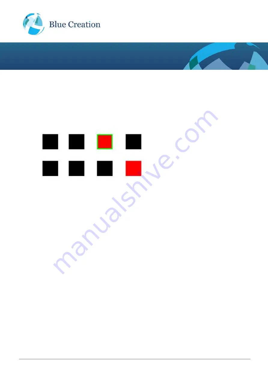
Each box on the represents a GPIO pin and indicates its direction (Input or output) and Logical state (High or
low):
Direction: A
green
border around a square indicates that this PIO is configured as an output rather than
an input. By default all PIOs are configured as inputs. No border around the square indicates that this PIO
is configured as input.
Logical State: The PIO state is indicated by the square colour:
black
means logical low and
red
means
logical high.
In this example:
P16: Input low
P17: Input low
P18: Input low
P19: Output high
P20: Input high
P21: Input low
P22: Input low
P23: Input low
Controlling GPIOs Using Melody Smart
To change a PIO's logical state from high to low and the other way press on the box representing the PIO.
To change a PIO's direction Press Edit and then press on the PIO - once direction changed press Done.


