2
Installation
7
Blue Seal Evolution Series GT45 / GT46 / GT60
©
Moffat Ltd, January 2007
Revision 1/
NOTE: It is important that adequately sized piping runs directly to the connection joint on the
appliance, with as few tees and elbows as possible to give maximum supply volume.
3.
A suitable joining compound which resists the breakdown action of LPG must be used on every gas
line connection, unless compression fittings are used.
The connection to the appliance is
3
/
4
” BSP male.
NOTE: A Manual Isolation Valve must be fitted to the individual appliance supply line.
4.
Correctly locate the appliance into its final operating position and using a spirit level, adjust the legs
so that the unit is level and at the correct height.
5.
Connect the gas supply to the appliance.
6.
Check gas operating pressure to as shown in the “Specifications” section. If the pressure is
incorrect, adjust the pressure by adjusting the regulator screw of the gas control valve as shown in
the ‘Gas Conversion and Specifications’ section.
7.
Check all gas connections for leakages using soapy water or other gas detecting equipment.
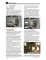
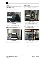
NOTE: The operating pressure is to be measured at the upper test point (Supply Pressure) on the
gas control valve located behind the access door and through the access hole in the control
panel, this is to be carried out with all burners operating at the “High Flame” setting.
8.
Turn ‘OFF’ the mains gas supply and bleed the
gas out of the appliance gas lines.
9.
Turn ‘ON’ the gas supply and the appliance.
10. Verify the operating pressure remains correct
(Re-adjust if required, using the operating
pressure adjusting screw as shown in the ‘Gas
Conversion and Specifications’ section).
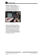
11. Check the pilot flame size. (Re-adjust if
required, using the pilot adjusting screw as
shown in the ‘Gas Conversion and
Specifications’ section).
WARNING:
D
O
NOT
USE
A
NAKED
FLAME
TO
CHECK
FOR
GAS
LEAKAGES
.
Supply Pressure
Test Point
Operating Pressure
Test Point
Pilot Burner
Adjusting Screw
Operating Pressure
Adjusting Screw


