Blue Ribbon BB4000 Instruction Manual Download Page 45

39

Model BB4000 Controller Instruction Manual

Return to Table of Contents

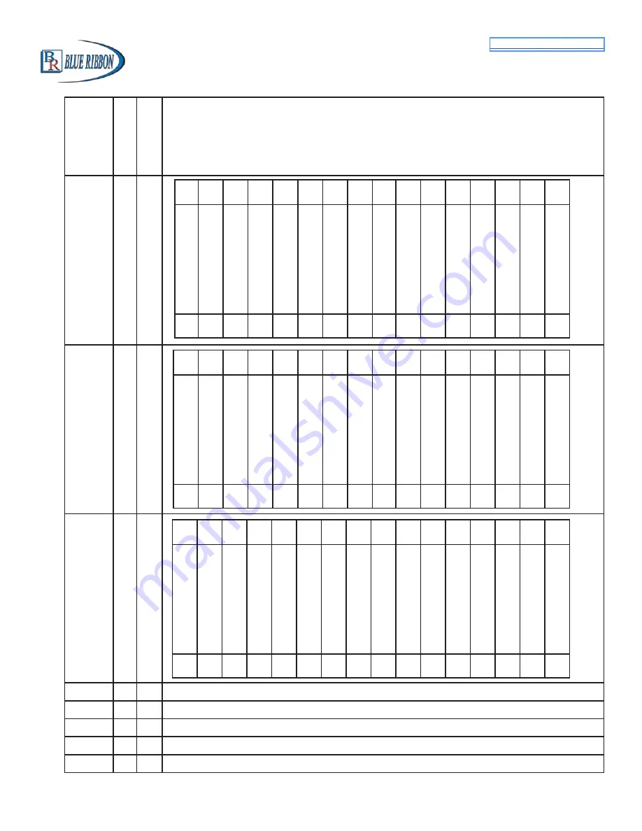
Description of Register Contents

(Where a Coil is represented by a Bit in a Register)

40008

Coil

Bit

40009

Coil

Bit

40010

Coil

Bit

40011

Wet Well Level (As shown on display with no decimal point)

40012

Setup Parameter - 1st Pump On Level

40013

Setup Parameter - 1st Pump Off Level

40014

Setup Parameter - 2nd Pump On Level

40015

Setup Parameter - 2nd Pump Off Level

Telemetry E

Discrete Input Function 19

Telemetry F

Discrete Input Function 20

Telemetry G

Discrete Input Function 21

Telemetry H

Discrete Input Function 22

All Pump Disable

Discrete Input Function 8

On Generator

Discrete Input Function 7

Off Level Float

Discrete Input function 33

High Level Float

Discrete Input Functions 18, 38

Low Level

(Level Probe Backup)

High Level

(Level Probe Backup)

4th Pump On Level Float

Discrete Input Function 36

3rd Pump On Level Float

Discrete Input Function 36

2nd Pump On Level Float

Discrete Input Function 35

1st Pump On Level Float

Discrete Input Function 34

Low Level Float Level 

Discrete Input Functions 17, 32

113

0

114

1

115

2

116

3

117

4

118

5

119

6

120

7

121

8

122

9

123

10

124

11

125

12

126

13

127

128

14

15

High Level (When Level is 

At or Above Alarm Setting)

Low Level (When Level is At 

or Below Alarm Setting)

Force Alternation

Start Flush Cycle

Stop Flush Cycle

Flush Cycle Active

129

0

130

1

131

2

132

3

133

4

134

5

135

6

136

7

137

8

138

9

139

10

140

11

141

12

142

13

143

144

14

15

Register

Address

Write

Write

Pump 1 Called to Run

Pump 2 Called to Run

Pump 3 Called to Run

Pump 4 Called to Run

Pump 1 Remote Control 

Disable Pump Operation

Pump 2 Remote Control 

Disable Pump Operation

Pump 3 Remote Control 

Disable Pump Operation

Pump 4 Remote Control 

Disable Pump Operation

145

0

146

1

147

2

148

3

149

4

150

5

151

6

152

7

153

8

154

9

155

10

156

11

157

12

158

13

159

160

14

15

Summary of Contents for BB4000

Page 1: ...email brsales blueribboncorp com Website www blueribboncorp com DISCLAIMER No representations or warranties are made with respect to the contents of this Instruction Manual Blue Ribbon Corp reserves t...

Page 2: ...nge a Setup Parameter Value 3 2 3 How to Simulate Levels 4 2 4 How to Enter the Security Code 4 3 Menu System Setup 5 4 Menu Data Display 10 5 Pump Call Sequence setup parameters 12 5 1 Number of Pump...

Page 3: ...s 18 8 1 Pump 1 2 3 4 Disable Functions 1 4 18 8 2 Level Freeze Function 5 18 8 3 External Alternation Function 6 18 8 4 On Generator Function 7 19 8 5 All Pump Disable Function 8 19 8 6 Sequence Inpu...

Page 4: ...6 Last Fault Code Parameter LFC 24 9 7 Fault Code Table 25 10 Analog Level Input 4 20 mA Input Calibration Procedure 27 10 1 Level Input Zero Parameter P 25 27 10 2 Level Input Span Parameter P 24 27...

Page 5: ...3 13 5 Flow Calculator Surface Area Calculation 34 13 6 Flow Calculator Display Parameters 34 14 Communication With a SCADA System 35 14 1 MODBUS Functions Supported 35 14 2 Setup for Connection to a...

Page 6: ...ctivity Indicator 46 19 2 Address of Last Slave Polled by Master 47 19 3 Record of Last Modbus Message 47 19 4 Communication Fault Codes 47 20 Connection Diagram 48 20 1 Standard Features 48 20 2 Conn...

Page 7: ...ump fault External Lead Pump Selector Switch All pump disable for connection to Phase Monitor Return to Table of Contents Limit number of pumps called while on emergency power Alternation by External...

Page 8: ...gulated 20Vdc 1V Transient Protected Analog Outputs Isolated 4 20mA Maximum Load Resistance 600 Auxiliary Analog Inputs Isolated 4 20mA 250 Load Transient Protected 1 5 Ordering Information Part Numbe...

Page 9: ...henever the indicator next to the Para meter label is on Parameters in the System Setup Sub Menu The value of the Parameter in the System Setup Sub Menu may be viewed by using the push button PB M to...

Page 10: ...PB S Note The Simulation starts from the actual level displayed prior to entering the Level Simulation mode 2 Press push button PB D or PB U as needed to change the simulated level 3 To end the level...

Page 11: ...ecurity Code may be Customized using Parameter P 26 See Page 6 P 13 4 Number of Pumps Present See Page 12 1 1 Pump 2 2 Pumps 3 3 Pumps 4 4 Pumps P 14 4 Number of Pumps Allowed to Run at the Same Time...

Page 12: ...5 1 sec Stop Pump Delay Range 1 100 seconds Note This is the Time Period that the Wet Well Level Must Remain At or Below At or Above for Pump UP P 19 2 the Respective OFF Level Setting in order to Tur...

Page 13: ...Telemetry Contact 23 Telemetry J Telemetry Contact 24 Telemetry K Telemetry Contact 25 Telemetry L Telemetry Contact 26 Telemetry M Telemetry Contact 27 Telemetry A Telemetry Contact 28 Telemetry B T...

Page 14: ...3 Speed Active When Pump 3 is Called 4 Pump 4 Speed Active When Pump 4 is Called 5 Speed Reference any Pump Always Active 6 Copy of Wet Well Level F 24 2 Analog Output 2 Function F 25 3 Analog Output...

Page 15: ...desired such as Pump Control 4TH On Level set the respective parameter equal to zero 3 An effective Backup Pump Control would involve having a 3 point Level Probe placed high in the wet well The Level...

Page 16: ...atus Value L 10 Electrode 10 Status Value L 11 Level Probe Test Signal Status Normal Range 230 254 Note This is a Measure of the 8v 60 Hz Square Wave Sent Out to Each Electrode to read the level If th...

Page 17: ...e 0 255 Where 0 0 0 mA 51 4 0 mA 255 20 mA Note Auxiliary Analog Input data may be read by SCADA in either an 8 Bit or 10 Bit format See Page 30 n 20 Auxiliary Analog Input 2 Status n 21 Auxiliary Ana...

Page 18: ...uate electrical power running all available pumps at the same time may be a problem This Parameter is used to set an upper limit on the number of pumps called to run at the same time If there is no ne...

Page 19: ...s a corresponding Pump Off Level setting for each of the Pump On Level settings For the Pump Stop Mode feature to operate the Pump Off Level settings must be set on different levels If all the Pump Of...

Page 20: ...tting Parameter P 39 on 1 will cause a fixed pump call sequence of 1 2 3 4 Parameter P 39 may also be changed by writing a 0 1 2 3 or 4 to SCADA Register 40022 Parameter Default Value Setting Definiti...

Page 21: ...Same as Parameter P 39 9 Parameter P 51 may be used to select and setup Time Based Alterna tion 7 2 Pump 1 Always Lead Stays On With Other Pumps Parameter P 16 2 NOTES 1 This sequence is used when it...

Page 22: ...Alternation would normally be disabled by setting Parameter P 18 to Disabled 9 If connected to a SCADA system alternation may be initiated by momen tarily setting Coil 136 or by forcing the lag pump...

Page 23: ...nificant difference in the size of the pumps and when only one pump is to be allowed to run at a time When there is a need for more pumping the smaller pump is turned off and the next larger pump is c...

Page 24: ...eded The one exception to this is the Alternation Sequence Pump 1 Always Lead Parameter P 16 3 where disabling pump 1 will not result in another pump taking its place 8 2 Level Freeze Function 5 When...

Page 25: ...must expire between each one called to run 8 6 Sequence Input 1 2 3 4 Functions 9 12 When a Discrete Input programmed as a Sequence Input 1 2 3 4 is closed it disables normal alternation and forces on...

Page 26: ...ator will come on and Fault Code 15 will be generated However this Function does allow pump operation from Float Backup using Functions 32 38 or Level Probe Backup using Parameters b 01 b 07 This Func...

Page 27: ...Up mode See Page 55 8 14 Float Backup 1st On Level Function 34 When a discrete Input programmed for Float Backup 1st On Level closes the Float Backup logic will issue one pump call assuming that the F...

Page 28: ...oes not matter how long the input remains closed but it must be opened to reset the logic Typically this input is connected to con tacts from an external Time Clock See Page 31 9 System Status 9 1 Hig...

Page 29: ...ess it is disabled using Parameter P 50 Low Level Alarm operation may be disabled by setting Parameter P 50 0 This disables Low Level Alarm operation from either the Analog Level Input Parameter F 19...

Page 30: ...Fault Code Parameter LFC is a copy of the last non zero Fault Code that was present in Parameter FLC Parameter LFC is reset when power is cycled or may be reset by pressing the down push button while...

Page 31: ...Minimum Speed is set too close to Level at 100 speed They must be at least 0 5 feet apart with P 36 1 or 5 feet with P 36 0 or 0 05 feet with P 36 2 12 VFD Speed Reference Setup Fault Level at Minimu...

Page 32: ...before Electrode 5 25 Electrode 5 Covered before Electrode 6 26 Electrode 6 Covered before Electrode 7 27 Electrode 7 Covered before Electrode 8 28 Electrode 8 Covered before Electrode 9 29 Electrode...

Page 33: ...ed up using Parameter P 49 10 1 Level Input Zero Parameter P 25 This parameter is used to make the display read zero feet of water with a Wet Well Level input of 4 0mA Calibration Procedure 1 Apply a...

Page 34: ...under 5 Repeat the procedure above for the LEVEL INPUT ZERO Parameter 10 3 Level Display Span VS Transducer Calibration Transducer Calibration 4 33 PSI 20mA 5 0 PSI 20mA 10 PSI 20mA 15 PSI 20mA 30 PSI...

Page 35: ...Default Value Current Value Setting Definitions P 20 50 Minimum speed Percent of Full Speed Range 0 95 P 21 3 5 feet Level at Minimum Speed Range 0 1 99 9 feet P 22 6 0 feet Level at 100 Speed Range 0...

Page 36: ...an addition al pump is called The pump speed stays at 100 for the time set on the Parameter P 23 then the pump speed returns to normal This feature may be used in cases where a pump is started at a s...

Page 37: ...Run at the Same Time B Closed Discrete Inputs that are Programmed for Pump 1 2 3 4 Disable or All Pump Disable 5 All backup systems must be setup so that they do not activate within the Flush Cycle o...

Page 38: ...7 days are all kept stored These flow totals are added together and divided by 7 This value is displayed as either Gallons Per Day or Thousand Gallons Per Day See Parameter P 45 The Average Daily Inf...

Page 39: ...t faster than 1 foot in 15 seconds with Parameter F 19 1 or faster than one Level Probe Electrode spacing in 15 seconds with Parameter F 19 2 or 3 the logic aborts the measurement and keeps the previo...

Page 40: ...5 2 Average Daily Inflow Total FdH FdL FdH FdL SCADA Register 40081 Thousand Gallons Gallons Per Day Million Gallons Thousand Gallons Per Day Note If Fault Code 36 Appears Average Daily Inflow Total i...

Page 41: ...Value Setting Definitions P 28 1 Slave Address See note 1 below Range 0 247 P 33 1 Register Access Mode 1 Read Write See note 2 below 2 Read Only 14 2 Setup for Connection to a SCADA System Notes 1 E...

Page 42: ...Bits Parameter values of the two devices must be set to match The Delay Before Response Parameter P 32 is provided for cases where the modem needs additional time to prepare itself before receiving a...

Page 43: ...11 IP Address Range 0 255 Identifier for the device on an IP network E 44 E 41 255 255 255 0 E 44 E 43 E 42 E 41 Subnet Mask Range 0 255 Range of IP addresses that can be Directly connected in the net...

Page 44: ...4 Remote Control Force Pump On ETM 1 Reset ETM 2 Reset ETM 3 Reset ETM 4 Reset Hi Relay Remote Control With Parameter F 31 2 LO Relay Remote Control With Parameter F 32 2 P1 Relay Remote Control With...

Page 45: ...mp On Level Float Discrete Input Function 36 3rd Pump On Level Float Discrete Input Function 36 2nd Pump On Level Float Discrete Input Function 35 1st Pump On Level Float Discrete Input Function 34 Lo...

Page 46: ...Reference Percent of Full Speed 0 100 Same as Parameter d 04 40040 Pump 3 VFD Speed Reference Percent of Full Speed 0 100 Same as Parameter d 05 Register Address Write Read Discrete Input 17 Discrete...

Page 47: ...1023 40073 Auxiliary Analog Input 3 10 Bit 0 1023 40074 Auxiliary Analog Input 4 10 Bit 0 1023 40080 Flow Calculator Latest Inflow Rate Gallons Per Minute Same as Param FLH FLL 40081 Flow Calculator A...

Page 48: ...1 If SCADA communication is lost Register 40025 will no longer receive current level data With the loss of communication the Controller will turn off all pumps and turn on the Fault indicator and plac...

Page 49: ...ster 40010 To return a pump to normal operation clear the respective Coil Upon a loss of serial communication the Pump Disable Logic will be automatically reset and any pump that had been remotely dis...

Page 50: ...ill be made lead A lead pump selector switch connected to discrete inputs programmed as sequence inputs will also override what is written to Register 40022 The setting may also be changed at Paramete...

Page 51: ...Alarm is generated when liquid covers the High Level Electrode of a Level Probe Input Parameter b 07 must be setup with the number of the Level Probe Input used to read the High Level The status of th...

Page 52: ...run times should be made and the registers should reset to zero The ETM data is stored in non volatile memory just prior to a total loss of internal 5V power so the data is not lost during a power out...

Page 53: ...ntire Modbus message will be present in data Parameters d 08 d 86 If the Slave Address is not acceptable or if any of these errors are encountered the rest of the message is rejected and does not show...

Page 54: ...48 Model BB4000 Controller Instruction Manual Return to Table of Contents 20 Connection Diagram 20 1 Standard Features...

Page 55: ...49 Model BB4000 Controller Instruction Manual Return to Table of Contents 20 2 Connection Diagram Optional Analog I O...

Page 56: ...50 Model BB4000 Controller Instruction Manual Return to Table of Contents 20 3 Connection Diagram Lead Pump Selector Switch...

Page 57: ...51 Model BB4000 Controller Instruction Manual Return to Table of Contents 20 4 Connection Diagram Analog Level Input 4 20mA Input...

Page 58: ...52 Model BB4000 Controller Instruction Manual Return to Table of Contents 20 5 Connection Diagram Level Probe...

Page 59: ...53 Model BB4000 Controller Instruction Manual Return to Table of Contents 20 6 Level Probe Placement and Setup...

Page 60: ...54 Model BB4000 Controller Instruction Manual Return to Table of Contents 20 7 Control Schematic Example Duplex with 24V Float Backup...

Page 61: ...55 Model BB4000 Controller Instruction Manual Return to Table of Contents 20 8 Float Backup Example Pump Down...

Page 62: ...bove the float The Low Level float must close as the level drops below the float 2 Pump Up Applications Parameter P 19 2 Two Float Backup A simple two float backup system can be made using an Off floa...

Page 63: ...57 Model BB4000 Controller Instruction Manual Return to Table of Contents 20 9 Operator Interface...

Page 64: ...58 Model BB4000 Controller Instruction Manual 20 10 Enclosure Mechanical Layout Return to Table of Contents Left Side Rear View Right Side Top View...

Page 65: ...59 Model BB4000 Controller Instruction Manual 20 11 Panel Cutout Return to Table of Contents Not Printed to Scale Do Not Use as a Template...

Page 66: ...which developed under normal installation use and service and 5 Blue Ribbon Corp is notified in advance of and approves the return by issuing a Return Material Authorization Number and the products ar...

Page 67: ...on Manual Blue Ribbon Corporation 2770 Long Road Grand Island NY 14072 U S A Tel 716 773 9300 Toll Free 877 774 4751 Fax 716 773 5019 email sales blueribboncorp com Visit our website www blueribboncor...

Reviews: