background image

ProxySG 900 Series Maintenance & Upgrade Guide

59

Processor (CPU)

4.

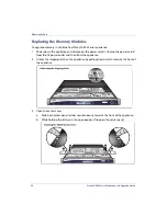
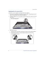
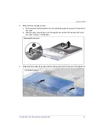
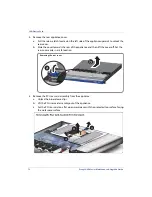
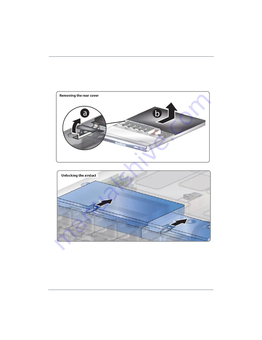
Remove the rear appliance cover.

a.

Pull the release latch located on the left side of the appliance upwards to unlock the 
rear cover.

b.

Slide the cover towards the rear of the appliance and then lift the cover off. Set the 
rear cover aside in a safe location.

5.

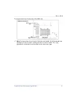
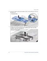
Unlock the the airduct by pushing the two locking clips towards the rear of the appliance.

Summary of Contents for ProxySG SG900-10

Page 1: ...B E T A D R A Blue Coat ProxySG Maintenance and Upgrade Guide ProxySG 900 Series Document Number 231 03166 Rev B 2...

Page 2: ...EE DS APPLIANCE SEE EVERYTHING KNOW EVERYTHING SECURITY EMPOWERS BUSINESS BLUETOUCH the Blue Coat shield K9 and Solera Networks logos and other Blue Coat logos are registered trademarks or trademarks...

Page 3: ...CD Display and LEDs 27 Fan Assembly Pre Installation Checklist 29 Replacing the Fan Assembly 30 Verifying Fan Installation 33 Hard Disk Drive Pre Installation Checklist 35 ProxySG 900 Upgrade Kit 36 P...

Page 4: ...stallation 55 Processor CPU Pre Installation Checklist 57 Replacing the Processor CPU 58 Verifying CPU Installation 66 LAN Option Card Pre Installation Checklist 67 Option Card Listing 68 Replacing th...

Page 5: ...ose a Rack Mounting Option 90 Prepare the Equipment Rack 91 Prepare the Appliance 92 Slide Rail Disassembly 92 4 Post Rail Installation 94 2 Post Mid Mount Rail Assembly 96 2 Post Front Mount Rail Ass...

Page 6: ...6 ProxySG 900 Series Maintenance Upgrade Guide...

Page 7: ...install field serviceable components and appliance upgrade kits for the ProxySG 900 Series appliance Important Review the Safety Warnings and Cautions on page 8 before servicing your appliance Online...

Page 8: ...roduct contains no user serviceable parts Do not open the power supply Hazardous voltage current and energy levels are present inside the power supply Return to manufacturer for servicing Toavoidrisko...

Page 9: ...ug power supply unplug the power cord to the power supply being replaced before removing the power supply from the server CAUTION Iftheserverhasbeenrunning anyinstalledprocessor s andheatsink s maybeh...

Page 10: ...wearing an antistatic wrist strap attached to chassis ground any unpainted metal surface on your server when handling parts Always handle boards carefully They can be extremely sensitive to ESD Hold...

Page 11: ...products proxysg Full Proxy Edition also known as Proxy Edition or http www bluecoat com products mach5 Acceleration Edition also known as MACH5 Specification SG900 10 SG900 10B SG900 20 SG900 30 Sys...

Page 12: ...ESD Wriststrap 1 Information flyer See Upgrading from the SG900 10 to a SG900 20 on page 15 UPG KIT SG900 10 to 30 M5 UPG KIT SG900 10 to 30 PR Upgrades the SG900 10 to the SG900 30 model Both upgrad...

Page 13: ...Power supply unit 1 ESD Wriststrap 1 Information flyer See Upgrading from the SG900 10B to a SG900 55 on page 19 UPG KIT SG900 20 to 30 M5 UPG KIT SG900 20 to 30 PR Upgrades the SG900 20 to the SG900...

Page 14: ...C3 10600 modules 1 1 TB SAS HDDs w carriers 1 ESD Wriststrap 1 Information flyer See Upgrading from the SG900 30 to a SG900 45 on page 23 UPG KIT SG900 30 to 55 M5 UPG KIT SG900 30 to 55 PR Upgrades t...

Page 15: ...00 10 to a SG900 20 Upgrade Steps Description 1 Archive the configuration and keyring that are running on the old appliance and record your network configuration settings See Chapter 5 Backing Up the...

Page 16: ...ide for additional information 3 Install a second power supply unit See Power Supply Unit on page 43 4 Replace all existing HDDs See Hard Disk Drive on page 35 5 Replace existing memory modules See Me...

Page 17: ...ide for additional information 3 Install a second power supply unit See Power Supply Unit on page 43 4 Replace all existing HDDs See Hard Disk Drive on page 35 5 Replace existing memory modules See Me...

Page 18: ...information 2 Install a second power supply unit See Power Supply Unit on page 43 3 Add additional HDDs See Hard Disk Drive on page 35 4 Replace existing memory modules See Memory Module on page 47 5...

Page 19: ...uide for additional information 3 Install a second power supply unit See Power Supply Unit on page 43 4 Replace all existing HDDs See Hard Disk Drive on page 35 5 Replace existing memory modules See M...

Page 20: ...nformation 2 Install a second power supply unit See Power Supply Unit on page 43 3 Add additional HDDs See Hard Disk Drive on page 35 4 Replace existing memory modules See Memory Module on page 47 5 R...

Page 21: ...nformation 2 Install a second power supply unit See Power Supply Unit on page 43 3 Add additional HDDs See Hard Disk Drive on page 35 4 Replace existing memory modules See Memory Module on page 47 5 R...

Page 22: ...ide for additional information 3 Install a second power supply unit See Power Supply Unit on page 43 4 Replace all existing HDDs See Hard Disk Drive on page 35 5 Replace existing memory modules See Me...

Page 23: ...iesQuickStartGuide for additional information 2 Add additional HDDs See Hard Disk Drive on page 35 3 Replace existing memory modules See Memory Module on page 47 4 Replace the existing CPU and heatsin...

Page 24: ...Configuration of the SGOS AdministrationGuide for additional instructions 3 Power down the appliance See the ProxySG900 SeriesQuickStartGuide for additional information 4 Replace all existing HDDs Se...

Page 25: ...settings See Chapter 5 Backing Up the Configuration of the SGOS AdministrationGuide for additional instructions 3 Power down the appliance See the ProxySG900 SeriesQuickStartGuide for additional infor...

Page 26: ...his Guide 26 ProxySG 900 Series Maintenance Upgrade Guide ProxySG 900 Series System Diagrams The following illustration shows the front and back of the ProxySG 900 Series appliance and motherboard com...

Page 27: ...er The appliance is on but the OS has not loaded Green The OS has loaded and is properly configured Amber to green blinking The OS has loaded but is not configured Off The appliance is powered off Sys...

Page 28: ...About This Guide 28 ProxySG 900 Series Maintenance Upgrade Guide...

Page 29: ...five system fan units Note The fan assemblies are hot swappable you can remove and replace a faulty fan assembly while the appliance remains powered on The fan assemblies are numbered from left to rig...

Page 30: ...ress 8082 where ip_address is the IP address assigned to the appliance b In the Management Console navigate to Maintenance System and Disks Environment c Click the View Sensors button to display a tab...

Page 31: ...ipping latch on the appliance by pulling the blue latch towards the front of the appliance 3 Open the center cover a Slide both center panel latches simultaneously towards the front of the appliance b...

Page 32: ...unit aside 5 Align the rubber grommets on the new fan unit with the chassis fan mounting points Verify that the fan arrows point towards the rear of the appliance An arrow indicating airflow direction...

Page 33: ...tallation To verify the health of the replaced fan assembly follow the instructions below 1 In the Management Console navigate to Maintenance System and Disks Environment 2 Click the View Sensors butt...

Page 34: ...34 ProxySG 900 Series Maintenance Upgrade Guide Fan Assembly...

Page 35: ...ur appliance start with ProxySG 900 Upgrade Kit on page 36 Note The HDDs are hot swappable you can remove replace or add HDDs while the appliance remains powered on Pre Installation Checklist The imag...

Page 36: ...00 20 900 10 to 900 30 1 RemoveexistingHDDsfromdrive bays one and two 2 Install upgrade HDDs into drive bays one and two RemovingaHardDiskDrive HDD Assembly onpage38 Installing a Hard Disk Drive HDD A...

Page 37: ...r take a disk offline 1 Select the Maintenance System and disks Disks tab Information displays for each present disk 2 To take a disk offline select a disk and click the Take disk x offline button whe...

Page 38: ...ng a Hard Disk Drive HDD Assembly To replace a HDD in a ProxySG 900 Series appliance 1 Open the bezel to access the hard disk drive quick release carriers Be sure to support both sides when flipping o...

Page 39: ...ance Upgrade Guide 39 Hard Disk Drive 3 Pull out the HDD carrier a short amount from the appliance using the carrier latch handle Once the HDD carrier body is in view fully remove the carrier while su...

Page 40: ...ce until it reaches the chassis stops Note Do not insert the HDD carrier with the latch in the closed position instead push the HDD carrier body 2 After the drive is in place secure the drive by closi...

Page 41: ...1 CLI See Using the CLI to Verify Disk Drive Installation on page 42 Using the Management Console to Verify Disk Drive Installation The following procedure describes how to use the Management Console...

Page 42: ...nfigured open an SSH session to the CLI and go to Step 2 b If you replaced the only disk drive in the appliance and have not yet configured it connect to the appliance serial console and configure the...

Page 43: ...wappable you can remove and replace a faulty power supply while the appliance remains powered by the other power supply Pre Installation Checklist Item Description Tools Required None Components Suppl...

Page 44: ...disk 1 Check for a faulty power supply a Log in to the appliance https ip_address 8082 where ip_address is the IP address assigned to the appliance b In the Management Console navigate to Maintenance...

Page 45: ...ced Unplug the power cord from the AC power outlet and then from the appliance 2 Depress the latch A and pull handle B to remove the power supply from the appliance 3 Insert the new power supply into...

Page 46: ...Supply Unit Verifying Power Supply Installation 1 In the Management Console navigate to Maintenance System and Disks Environment 2 Click the View Sensors button to display a table that shows power sup...

Page 47: ...les in a Blue Coat ProxySG 900 Series appliance Pre Installation Checklist Item Description Tools Required None Components Supplied Matched DIMM set Other Required Components None Safety Notices See S...

Page 48: ...liance look at the appliance memory configuration for the target specification and review the DIMM slot usage for each memory module Memory should always be installed in matched pairs of equal size an...

Page 49: ...below shows the location of the DIMM slots Note The image above shows how matched memory modules should be grouped one matched set in slots A1 and B1 and the second set in slots A2 and B2 This is onl...

Page 50: ...onnect the power cord s Unplug the power cord s from the AC power outlet and then from the appliance 2 Unlock the shipping latch on the appliance by pulling the blue latch towards the front of the app...

Page 51: ...ll the release latch located on the left side of the appliance upwards to unlock the rear cover b Slide the cover towards the rear of the appliance and then lift the cover off Set the rear cover aside...

Page 52: ...rduct by releasing the hold down tab a and then lifting from the appliance b 7 Remove all of the existing memory do not mix existing DIMMs with the included replacement DIMMs Depress both of the locki...

Page 53: ...To install the new memory align the notch in the DIMM with the DIMM slot Be aware that the memory module can only be installed in one direction 9 Press each DIMM firmly into place until both locking l...

Page 54: ...air duct with corresponding mounting pins on the chassis 11 Lock into place by pushing the two pins towards the front of the appliance 12 Reinstall the appliance s middle and back panels 13 Reinstall...

Page 55: ...ory Module Verifying Memory Installation In the Management Console navigate to Maintenance System and Disks The Summary tab displays the amount of memory installed Verify that the total amount of memo...

Page 56: ...56 ProxySG 900 Series Maintenance Upgrade Guide Memory Module...

Page 57: ...appliance Pre Installation Checklist Item Description Tools Required 2 Phillips head screwdriver Components Supplied CPU Heatsink with thermal adhesive Other Required Components None Safety Notices Se...

Page 58: ...sconnect the power cord s Unplug the power cord s from the AC power outlet and then from the appliance 2 Unlock the shipping latch on the appliance by pulling the blue latch towards the front of the a...

Page 59: ...release latch located on the left side of the appliance upwards to unlock the rear cover b Slide the cover towards the rear of the appliance and then lift the cover off Set the rear cover aside in a...

Page 60: ...y releasing the hold down tab a and then lifting the airduct from the appliance b 7 Remove the heat sink by unscrewing 4 screws using a 2 Phillips head screwdriver a and lifting the heatsink off the a...

Page 61: ...and away from the socket and then lifting the lever The processor load plate automatically opens Caution Do not touch the processor socket contact points 9 Remove the processor by lifting it straight...

Page 62: ...ns with the triangle etched along the socket on themotherboard Holdthetop and bottom edges of the processor and set it into the socket by moving it vertically into place Verify that the processor has...

Page 63: ...it comes pre applied with a thermal pad Do not touch or apply additional thermal materials onto the heatsink 14 Set the heat sink into position by aligning the screw mount tabs on the heatsink with th...

Page 64: ...tsink screws Lightly install the screws using an alternating pattern to distribute the load across the mounting surface After all screws are in place tighten the heatsink screws Do not overtighten 16...

Page 65: ...the airduct into place by pushing the two locking clips towards the front of the appliance 18 Reinstall the appliance s middle and back panels 19 Reinstall the appliance cabling a Reconnect the networ...

Page 66: ...g CPU Installation In the Management Console navigate to Maintenance System and Disks The Summary tab displays the number of CPU cores installed Note The CPUs installed line displays the total number...

Page 67: ...Series appliance is equipped with two expansion slots with support for one full length and one half length card Pre Installation Checklist Item Description Tools Required None Components Supplied Upg...

Page 68: ...age the appliance and will invalidate your warranty Next If you are installing a full length option card into your appliance see Installing a Long Option Card on page 73 If you are installing a half l...

Page 69: ...e To install the option card into your appliance you will need to replace the existing bracket with one of the included appliance specific brackets To replace the standard full profile bracket with th...

Page 70: ...900 Series Maintenance Upgrade Guide LAN Option Card 2 Install the ProxySG 900 bracket using the same Phillips head screws that were removed in the previous step The option card is in the upside down...

Page 71: ...connect the power cord s Unplug the power cord s from the AC power outlet and then from the appliance 2 Unlock the shipping latch on the appliance by pulling the blue latch towards the front of the ap...

Page 72: ...Slide the cover towards the rear of the appliance and then lift the cover off Set the rear cover aside in a safe location 5 Remove the PCI riser card assembly from the appliance a Unlock the blue rele...

Page 73: ...ng Option Card 1 Remove the short expansion slot cover from the PCI riser card by pressing the release button a and then pulling out the cover from the side b Set the expansion slot cover aside in a s...

Page 74: ...he card and gently inserting into the long option card PCI slot It might be necessary to lightly rock the option card into position Verify that the PCI card has been fully seated and is aligned with t...

Page 75: ...lly seated b Lock the PCI riser card into place by pressing down on the blue release clips while pressing down into the chassis 6 Reinstall the appliance s middle and back panels 7 Reinstall the appli...

Page 76: ...ort Option Card 1 Remove the short expansion slot cover from the PCI riser card by pressing the release button a and then pulling out the cover from the side b Set the expansion slot cover aside in a...

Page 77: ...the card and gently inserting into the long option card PCI slot It might be necessary to lightly rock the option card into position Verify that the PCI card has been fully seated and is aligned with...

Page 78: ...ully seated b Lock the PCI riser card into place by pressing down on the blue release clips while pressing down into the chassis 6 Reinstall the appliance rear and center panels 7 Reinstall the applia...

Page 79: ...79 LAN Option Card Verifying Option Card Installation 1 In the Management Console navigate to Configuration Network Adapters 2 In the Physical Interfaces panel list the additional interfaces are disp...

Page 80: ...elect the bridge you want to configure 3 Click Edit The Edit Bridge dialog displays 4 Select a bridge mode from the Mode drop down The following bridge modes are available Disabled Disables the bridge...

Page 81: ...battery on the ProxySG 900 Series appliance Pre Installation Checklist Item Description Tools Required None Components Supplied 3V BIOS Battery Other Required Components None Safety Notices See Safet...

Page 82: ...onnect the power cord s Unplug the power cord s from the AC power outlet and then from the appliance 2 Unlock the shipping latch on the appliance by pulling the blue latch towards the front of the app...

Page 83: ...ear of the appliance and then lift the cover off Set the rear cover aside in a safe location 5 Remove the PCI riser card assembly from the appliance a Unlock the blue release clips b Lift the PCI rise...

Page 84: ...ve the existing BIOS battery release the battery by pressing the clip with the flat blade screwdriver The battery should tilt upward slightly out of the battery holder Remove the battery If necessary...

Page 85: ...er retaining clip and then press down to secure it 9 Re install the PCIe riser card SSL card unit back into the appliance and screw into place 10 Re install the appliance s top cover Finalize the BIOS...

Page 86: ...86 ProxySG 900 Series Maintenance Upgrade Guide BIOS Battery...

Page 87: ...ipmentrackguideformore information Marker Pen optional Mechanical lift optional Components Supplied Slide Rail Kit consisting of the following components 2 Pre assembled slide rails each Rail_A assemb...

Page 88: ...usions 4 Post Racks For any industry standard 4 post equipment rack Appliances mounted using the 4 post method benefit from greater stability because they are supported on all four corners Blue Coat r...

Page 89: ...can be performed by a single technician however if a mechanical lift is not used BlueCoat recommends the assistance of two additional technicians Step Description Page 1 Choose a Rack Mounting Option...

Page 90: ...19 inch equipment rack in 2 and 4 post configurations The slide rail kit is fully adjustable and can also accommodate standard 4 post equipment racks Users who choose the 2 post rail installation can...

Page 91: ...inet be sure it has sufficient depth to accommodate the unit e TIP Installing the appliance lower in the equipment rack offers easier installation and better service access 2 Prepare the equipment rac...

Page 92: ...bly The slide rail kit comes with the inner rail preattached to Rail_A and must be disassembled before continuing with the installation To remove the inner rail from Rail_A 1 Fully extend the slide ra...

Page 93: ...ll 1 M3 screw to secure the inner rail onto the appliance 4 Repeat steps 1 3 to install the slide on the opposite side of the appliance Set the appliance aside in a safe location after attaching the i...

Page 94: ...g faces against the vertical equipment rails Install screws into the mounting points on the opposite ends on the slotted hole on Rail_C Be sure to use at least a total of 3 screws Note If the Rail_A a...

Page 95: ...fully tighten The Rail_C bracket will be tightened after the appliance is secured in the rack c Tighten the Rail_C side mounting screws d Repeat steps 3a 3c on the opposite side Ensure both slide rai...

Page 96: ...not included with the slide rail kit as they are rack specific See your equipment rack installation guide for more information on screw sizing a Install the front Rail_B bracket with the mounting sur...

Page 97: ...le mounting points This will prevent alignment issues when attaching the opposite slide rail b Secure Rail_A to the Rail_B mounting brackets using M3 screws You can use any of the points that are avai...

Page 98: ...nd rail assembly onto the equipment rack 1 Install one Rail_B mounting bracket onto the rear face of the equipment rail Note The rack screws used in this step are not included with the slide rail kit...

Page 99: ...quipment rail b Secure Rail_A using 2 rack screws c Secure Rail_A to the Rail_B mounting bracket using M3 screws You can use any of the points that are available on the slotted holes Be sure to use at...

Page 100: ...ipment rack 1 Align the grooves of the inner rail with those on Rail_A and slide the appliance half way into the rack 2 Activate the white tab on the inner rail to slide the appliance fully into the e...

Page 101: ...n the equipment rack 3 With the appliance installed into the equipment rack push and pull the system to verify smooth movement across the entire range of motion Note If you experience difficulty slidi...

Page 102: ...that the vertical equipment rack rails be 450mm apart for the front and 451mm for the rear for proper fit and function as shown below In the rare instances that the equipment rails fall below the indi...

Page 103: ......

Page 104: ...www bluecoat com...

Reviews: