background image

INSTRUCTIONS FOR THE USE OF THE BRUSH-CUTTER 


4.3 

Correct use 


The brushcutter must be used only to cut grass, bushes and shrubbery (trunks with a max. diameter of 200 mm can be 
cut using a machine with elevated power equipped with both a blade and a trunk-retainer guard to CE standards). 


Wear the safety belts and adjust them to your height. 


After the engine has started, let it run for 2-3 minutes at the minimum level. 


Connect the brushcutter to the safety quick release clip on the safety belts, or if the brushcutter has been provided in 

the backpack version, wear it on your shoulders. 


Make sure that the weight of the machine is evenly distributed and perfectly balanced in such way that the cutting 

organ is parallel to the ground and does not require support from the grip. 


Perform a few accelerations (without reaching the maximum rpm) without doing work to make sure that everything 

is functioning regularly. 


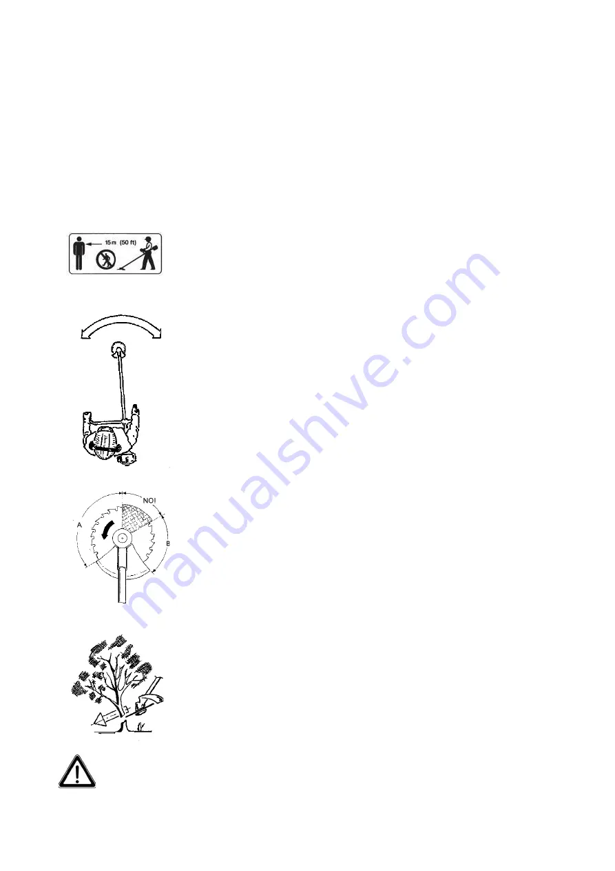
With the cutting tool stationary in clear sight and constantly under your control, reach 
the  work  position  by  carrying  the  machine  beneath  the  level  of  your  waist  far  away 
from your body, making sure that there are no other people within a 15 meter radius. 


4.4 

Use of the machine 


Fig.21 


Fig.22 


Fig.23 

Assume a stable and balanced position on both feet. 

Grass is cut 

as if operating in corridors 1.5 meters wide by moving forward step by step 

and swinging the machine right and left. Make sure that you are standing securely on both 
feet  before  taking  a  new  step  (Fig.  21).  When  using  the  grass-cutter  disks,  always  cut  
from right to left and leave a pile of cut grass on the left for subsequent recovery. 

When  using  the  machine  to  cut  bushes  or  pruning 

mount  the  CE-standard  disk  saw 

together with the appropriate safety guard. You will reach the maximum  cutting capacity 
when  the  acceleration  of  the  machine  is  at  its  peak  rpm  and  consequently  the  saw  will 
have  a  lower  probability  of  jamming  or  stopping  under  these  operating  conditions.  In 
order  to  use  this  type  of  cutting  tool  correctly,  the  blade  must  not  be  used  in  its  critical 
sector (Fig. 22), given the risk of the blade’s rebounding (known kick-back). This effect is 
sometimes strong enough to make you lose control of both the machine and your balance, 
with the consequent risk of injury. We recommend cutting with side A of the disk saw for 
ideal cutting control. Side B can also be used for cutting, but there is less control because 
of the disk counter-clock-wise rotation. 

The direction of the felling 

of the trunk depends on the sector of use of the disk  saw, a 

determined inclination of the blade, and the diameter of the trunk in question. 
-


For trunks of up to 3 cm in diameter, the disk saw can be used with “hatchet strokes”, in 

other words, cutting from the opposite side foreseen for the falling of the trunk. 
-


For trunks of from 3 to 7 cm in diameter, the disk saw must never be held horizontally, 

but always at a slight angle from upwards downwards to prevent the blade from jamming. 
The thicker the diameter of the trunk, the greater this inclination must be (Fig. 23). 
-


Trunks of more than 7 cm in diameter can be also felled with high-power brushcutter, 

but  this  operation  should  be  performed  only  occasionally  because  a  power  saw  is  more 
appropriate in cases such as these. 
Try to avoid even the smallest stones, piles of earth, small pieces of wood, and any other 
hidden objects in the grass. If you happen to strike some large object, if the cutting tool 
suddenly jams due to overloading, if too much grass, stringy vegetal matter or bark gets 
wound  up  inside  the machine,  reduce  the  speed  to  the  minimum  and  then  disengage  the 
clutch. 
Make sure that the blade (which turns through inertia) has come to a halt, otherwise stop it 
against the ground in a safe place and then switch off the engine. Unhook the brushcutter 
from  the  safety  belt  and  position  it  on  the  ground  in  order to  make  sure  that  the  cutting 
tool  has  not  undergone  any  damage,  such  as  the  cracking/  breakage  of  teeth,  etc.,  and 
replace if required. If the tool has got tangled up in stringy vegetal matter, put on a pair of 
gloves and use the correct utensil to completely remove all the tangled material. 

ALL T 
OPERA 

HE MACHINE’S SAFETY SYSTEMS AND EQUIPMENT MUST BE MAINTAINED IN 

TION ALL THROUGHOUT USE. 


GB - 16 

Summary of Contents for BBH 2600

Page 1: ...ZIONI ORIGINALI INSTRUCTIONS FOR THE USE OF THE BRUSH CUTTER ORIGINAL INSTRUCTIONS LEGGERE ATTENTAMENTE IL PRESENTE MANUALE PRIMA DI UTILIZZARE LA MACCHINA READ CAREFULLY THIS WORKBOOK BEFORE USING TH...

Page 2: ...abelle dei dati tecnici 6 3 0 ASSEMBLAGGIO 9 3 1 Assemblaggio dei modelli con asta rigida 9 3 2 Assemblaggio dei modelli con asta flessibile 10 3 3 Per tutti i modelli 10 3 4 Assemblaggio degli organi...

Page 3: ...e nel raggio d azione della macchina Usate sempre indumenti da lavoro idonei ed adeguati strumenti di protezione tute da lavoro aderenti scarpe pesanti guanti casco protettivo etc Indossate sempre occ...

Page 4: ...il tipo di abbigliamento e gli strumenti di protezione da indossare per utilizzare la macchina Usate tute da lavoro aderenti evitate di indossare camicioni o indumenti slacciati Evitate gioielli anel...

Page 5: ...urezza H Tuta da lavoro resistente I Supporto antivibrante L Manopola acceleratore con interruttore di STOP M Motore con protezioni per il calore C D M E I L F H G Fig 1 1 7 Usi non consentiti e contr...

Page 6: ...principali Fig 2 1 Serbatoio miscela 2 Impugnatura avviamento 3 Manubrio Impugnatura antivibrante 4 Supporto antivibrante 5 Leva comando gas con sicurezza 6 Asta trasmissione 7 Coppia conica 8 Organo...

Page 7: ...0 M Livello di pressione acustica LpA av in accordo con 2000 14 EC 2005 88 EC dB 93 91 92 92 91 92 92 90 87 84 90 Livello di potenza acustica LWA av in accordo con 2000 14 EC 2005 88 EC dB 113 111 112...

Page 8: ...0 I 420 M 330 I 420 M 330 I 420 M 330 I 420 M 330 I 420 M 330 I 420 M 330 I 420 M Livello di pressione acustica LpA av in accordo con 2000 14 EC 2005 88 EC dB 91 92 92 93 93 91 92 92 93 93 Livello di...

Page 9: ...M 330 I 420 M 475 475 330 I 420 M 450 T 330 I 420 M 475 330 I 420 M 475 Livello di pressione acustica LpA av in accordo con 2000 14 EC 2005 88 EC dB 87 93 5 93 92 93 92 91 91 91 92 92 Livello di pote...

Page 10: ...il lato pi lungo rivolto verso sinistra essa serve come barriera protettiva durante il lavoro in modo da prevenire un contatto involontario del corpo con l accessorio di taglio Prima di fissare le vi...

Page 11: ...i impugnatura che utilizzerete troverete nella dotazione l adeguata cinghia di sicurezza Nelle macchine dotate di manubrio essa composta da cinghia a tracolla con spallaccio fisso e da una protezione...

Page 12: ...ica part 1 il dado autobloccante part 7 la flangia part 5 Seguendo la fig B infilate il coperchietto anti avvolgente part 3 ed il disco di taglio part 4A sull albero filettato in uscita dalla cassa co...

Page 13: ...nte che nella versione con manubrio Per tutti gli altri dispositivi di taglio usare la macchina nella versione con manubrio Per l assemblaggio degli utensili da taglio con i rispettivi ripari proceder...

Page 14: ...ma tronchi La sega circolare fornita come OPTIONAL ed severamente vietato l utilizzo sul decespugliatore in oggetto Non utilizzate mai coltelli lame od organi di taglio differenti da quelli forniti da...

Page 15: ...lizzo della manopola Fig 17 dovete innanzitutto conoscerne le funzioni in questo modo potrete accendere la macchina e controllarne la velocit di lavoro Per motore modello TJ53E 1 SEMIACCELERAZIONE per...

Page 16: ...macchina indispensabile portare il pulsante rosso della manopola in posizione CENTRALE eseguite poi le varie operazioni di semiaccelerazione e accelerazione come spiegato precedentemente Per i decesp...

Page 17: ...ere il controllo della macchina del vostro equilibrio e di conseguenza ferirvi Consigliamo di effettuare il taglio con il lato A della sega circolare per avere un controllo ottimale dell operazione po...

Page 18: ...attenzione a non danneggiare il serbatoio con urti o tagli Nel riporre la macchina evitate urti o cadute a terra che potrebbero danneggiarla 6 0 MANUTENZIONE 6 1 Coppia conica Fig 24 Ogni 25 ore ingr...

Page 19: ...i i componenti da noi riconosciuti difettosi e sostituiti gratuitamente in garanzia saranno da noi trattenuti g Eventuali sostituzioni gratuite di componenti anche se da noi riconosciuti difettosi non...

Page 20: ...1 Main parts 5 2 2 Technical data tables 6 3 0 ASSEMBLY 9 3 1 Models with rigid shaft 9 3 2 Models with flexible shaft 10 3 3 For all modells 10 3 4 Fastening of cutting organs 12 4 0 USE OF THE MACHI...

Page 21: ...ast 15 meters away from the machine s radius of operation The operators must always use the appropriate protection means and wear close fitting work suits heavy duty shoes gloves and protective helmet...

Page 22: ...on means Carefully read the following instructions regarding the type of clothing and protection means prior to using the machine Wear close fitting work suits avoid wearing loose shirts or unfastened...

Page 23: ...Vibration damping support L Accelerator knob with STOP switch M Engine with overheating protection C D M E I L F H G Fig 1 1 7 Inappropriate use and contraindications The unit must be used for the pu...

Page 24: ...in parts Fig 2 1 Mixture tank 2 Starting grip 3 Vibration damping handle bar grip 4 Vibration damper support 5 Gas control knob lever with safety 6 Transmission rod 7 Bevel gear pair 8 Cutting tool 9...

Page 25: ...sound pressure LpA av according to 2000 14 EC 2005 88 EC dB 93 91 92 92 93 91 92 92 88 91 92 92 Level of sound power LWA av according to 2000 14 EC 2005 88 EC dB 113 111 112 112 113 111 112 112 112 1...

Page 26: ...420 M 330 I 420 M 330 I 420 M 330 I 420 M 330 I 420 M 330 I 420 M Level of sound pressure LpA av according to 2000 14 EC 2005 88 EC dB 91 92 92 93 93 91 92 92 93 93 Level of sound power LWA av accordi...

Page 27: ...475 475 330 I 420 M 450 T 330 I 420 M 475 330 I 420 M 475 Level of sound pressure LpA av according to 2000 14 EC 2005 88 EC dB 87 93 5 93 92 93 92 91 91 91 91 92 Level of sound power LWA av according...

Page 28: ...cross F by keeping the longer part facing left this serves as a protective barrier during operation that prevents involuntary contact of your body with the cutting accessory Before definitively tight...

Page 29: ...ng to the type of grip being used you will find the appropriate safety belt among those provided In models equipped with handle bars the safety belt is composed of a shoulder strap with a fixed should...

Page 30: ...g B Fixing get off from the gear case box part 1 the self locking nut part 7 the flange part 5 Following the pic B introduce the wrapping cover part 3 and the cutting plate part 4A in the threaded sha...

Page 31: ...n damping grip or the version with the handlebar For all other types of cutting element use the version of the machine with the handlebar Proceed as follows for the assembly of the cutting accessory w...

Page 32: ...y guard always mount the appropriate CE trunk retainer guard The disk saw is provided as OPTIONAL and it s severely forbbiden using it in this machine Never use knives blades or cutting elements other...

Page 33: ...s functions and in this way switch on the machine and keep the work speed under control For TJ53E engine 1 SEMI ACCELERATION FOR STARTING of cold engine model TJ53E Grip the gas control handle by pres...

Page 34: ...RAL position and then perform the acceleraration and semi acceleration operations as previously explained Choke lever only for engine TJ27E TJ35E TJ45E For brushcutters powered by engines TJ23E TJ27E...

Page 35: ...not be used in its critical sector Fig 22 given the risk of the blade s rebounding known kick back This effect is sometimes strong enough to make you lose control of both the machine and your balance...

Page 36: ...on it carefully on the ground to prevent falling that might cause damage 6 0 MAINTENANCE 6 1 Bevel gear pair Fig 24 Grease the bevel gear pair every 25 working hours by unscrewing the screw that serve...

Page 37: ...plugs etc f All the components we recognize faulty and replaced free of charge under warranty will be retained by us g Any replacements of components even if recognized faulty will not under any circu...

Page 38: ...ome da allegato V Sound Power Levels performed per annex V TIPO TYPE Livello di potenza sonora misurato Livello di potenza sonora garantito Measured Sound Power Level Guaranteed Sound Power Level LWA...

Page 39: ......

Page 40: ...BLUE BIRD INDUSTRIES Fabbrica Motori s r l Via Due Camini 19 36010 ZAN Vicenza ITALY Telefono 0445 314138 ric aut Telefax 0445 314225 http www bluebirdind com E mail info bluebirdind com 698970 202011...

Reviews: