background image

4 Clearview 4:2

User Manual


å

Elevated Operating Ambient - If installed in a closed or multi-unit rack assembly, 

the operating ambient temperature of the rack environment may be greater 

than room ambient. Therefore, consideration should be given to installing 

the equipment in an environment compatible with the maximum ambient 

temperature per Section 2.3.


å

Reduced Air Flow - Installation of the equipment in a rack should be such that 

the amount of air flow required for safe operation of the equipment is not 

compromised.


å

 Mechanical Loading - Mounting of the equipment in the rack should be such 

that a hazardous condition is not achieved due to uneven mechanical loading.


å

Circuit Overloading - Consideration should be given to the connection of 

the equipment to the supply circuit and the effect that overloading of the 

circuits might have on overcurrent protection and supply wiring. Appropriate 

consideration of equipment nameplate ratings should be used when addressing 

this concern.


å

Reliable Earthing - Reliable earthing of rack-mounted equipment should be 

maintained. Particular attention should be given to supply connections other 

than direct connections to the branch circuit (e.g. use of power strips).


å

Read all safety and operating instructions before you operate the unit.


å

Retain all safety and operating instructions for future reference.


å

Heed all warnings on the unit and in the safety and operating instructions.


å

Follow all installation, operating, and use instructions.


å

Unplug the unit from the AC power outlet before cleaning. Use only a damp 

cloth for cleaning the exterior of the unit.


å

Do not use accessories or attachments not recommended by Blonder Tongue, 

as they may cause hazards, and will void the warranty.


å

Do not operate the unit in high-humidity areas, or expose it to water or 

moisture.


å

Do not place the unit on an unstable cart, stand, tripod, bracket, or table. The 

unit may fall, causing serious personal injury and damage to the unit. Install the 

unit only in a mounting rack designed for 19” rack-mounted equipment.


å

Do not block or cover slots and openings in the unit. These are provided for 

ventilation and protection from overheating.  Never place the unit near or over 

a radiator or heat register. Do not place the unit in an enclosure such as a cabinet 

without proper ventilation. Do not mount equipment in the rack space directly 

above or below the unit.


å

Operate the unit using only the type of power source indicated on the marking 

label. Unplug the unit power cord by gripping the plug, not the cord.


å

 The unit is equipped with a three-wire ground-type plug. This plug will fit only 

into a ground-type power outlet. If you are unable to insert the plug into the 

outlet, contact an electrician to replace the outlet. Do not defeat the safety 

purpose of the ground-type plug.


å

 Route power supply cords so that they are not likely to be walked on or pinched 

by items placed upon or against them. Pay particular attention to cords at plugs, 

convenience receptacles, and the point where they exit from the unit.

WARNING: TO PREVENT FIRE OR SHOCK HAZARD, DO NOT EXPOSE THIS 

UNIT TO RAIN OR MOISTURE

NOTE TO CATV SYSTEM INSTALLER

This reminder is provided to call the CATV System Installer’s attention to 

Article 820-40 of the NEC that provides guidelines for proper grounding 

and, in particular, specifies that the cable ground shall be connected to 

the grounding system of the building, as close to the point of cable entry 

as practical.

TO REDUCE THE RISK OF ELECTRICAL SHOCK, DO NOT REMOVE COVER 

FROM THIS UNIT.

NO USER-SERVICEABLE PARTS INSIDE. REFER SERVICING TO QUALIFIED 

SERVICE PERSONNEL.

Section 1 – General & Safety Instructions

The STOP sign symbol is intended to alert you to the 

presence of REQUIRED operating and maintenance 

(servicing) instructions that if not followed, may result in 

product failure or destruction.

The  YIELD  sign  symbol  is  intended  to  alert  you  to  the 

presence of RECOMMENDED operating and maintenance 

(servicing) instructions.

The  LIGHTNING  flash  symbol  is  intended  to  alert  you 

to  the  presence  of  uninsulated  “dangerous  voltage” 

within the product's enclosure that may be of sufficient 

magnitude to constitute a risk of electrical shock.

You should always follow these Instructions to help ensure Against injury to yourself and damage to your equipment.
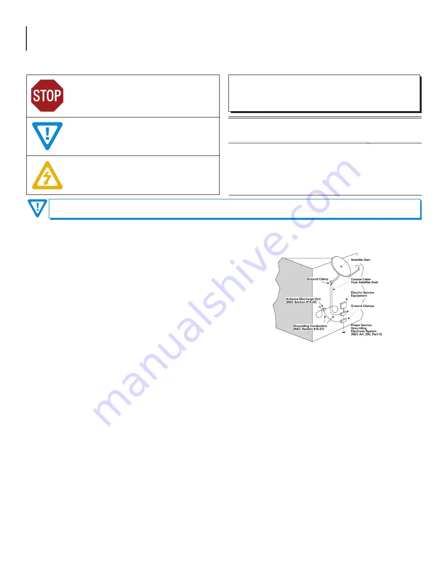
 

å

 Be sure that the outdoor components of the antenna system are grounded in 

accordance with local, federal, and National Electrical Code (NEC) requirements. 

Pay special attention to NEC Sections 810 and 820.  See the example shown in 

the following diagram:


å

We strongly recommend using an outlet that contains surge suppression or 

ground fault protection. For added protection during a lightning storm, or when 

the unit is left unattended and unused for long periods of time, unplug it from 

the wall outlet and disconnect the lines between the unit and the antenna. This 

will prevent damage caused by lightning or power line surges.


å

Do not locate the antenna near overhead power lines or other electric light 

or power circuits, or where it can fall into such power lines or circuits. When 

installing the antenna, take extreme care to avoid touching such power lines or 

circuits, as contact with them can be fatal.


å

Do not overload wall outlets or extension cords, as this can result in a risk of fire 

or electrical shock.


å

 Never insert objects of any kind into the unit through openings, as the objects 

may touch dangerous voltage points or short out parts. This could cause fire or 

electrical shock.


å

Do not attempt to service the unit yourself, as opening or removing covers may 

expose you to dangerous voltage and will void the warranty. Refer all servicing 

to authorized service personnel.


å

Unplug the unit from the wall outlet and refer servicing to authorized service 

personnel whenever the following occurs:


o

The power supply cord or plug is damaged;


o

Liquid has been spilled, or objects have fallen into the unit;


o

The unit has been exposed to rain or water;


o

The unit has been dropped or the chassis has been damaged;


o

The unit exhibits a distinct change in performance.


å

When replacement parts are required, ensure that the service technician uses 

replacement parts specified by Blonder Tongue. Unauthorized substitutions 

may damage the unit or cause electrical shock or fire, and will void the warranty.


å

 Upon completion of any service or repair to the unit, ask the service technician 

to perform safety checks to ensure that the unit is in proper operating condition.

Summary of Contents for Clearview 4:2

Page 1: ...All Rights Reserved Specifications subject to change without notice All trademarks are property of their respective owners H 264 to MPEG 2 HD Transcoder for up to 24xSPTS Channels Blonder Tongue Labs Inc ISO 9001 2015 Certified P N 651245300A Rev 112119 Clearview 4 2 User Manual ...

Page 2: ...e or Stock Number in the search field Upon reaching the product page the User Manual download link will be located beneath the product image Firmware Updates are available under Tech Support in the Resources section of the website General instructions for the FTP site as well as updating your firmware are provided on this page We recommend that you write the following information in the spaces pro...

Page 3: ...ALLATION AND POWER UP 8 SECTION 4 CONNECTING TO A PC LAPTOP 8 4 1 ETHERNET ACCESS 8 4 2 ACCESSING THE USER INTERFACE VIA THE WEB BROWSER 9 SECTION 5 BASIC CONFIGURATION 10 5 1 STATUS SCREEN 10 5 2 SYSTEM SCREEN 11 5 3 TIME SCREEN 13 5 4 ADMIN SCREEN 14 SECTION 6 TRANSCODERS 15 6 1 TRANSCODERS STATUS SCREEN 15 6 2 TRANSCODERS SETTINGS SCREEN 15 SECTION 7 FIRMWARE UPDATES AND TROUBLESHOOTING 18 7 1 ...

Page 4: ... This reminder is provided to call the CATV System Installer s attention to Article 820 40 of the NEC that provides guidelines for proper grounding and in particular specifies that the cable ground shall be connected to the grounding system of the building as close to the point of cable entry as practical TO REDUCE THE RISK OF ELECTRICAL SHOCK DO NOT REMOVE COVER FROM THIS UNIT NO USER SERVICEABLE...

Page 5: ...rview 4 2 provides an easy to use interface and the ability to download and upload a configuration file for multi unit deployments TheClearview4 2canalsobeconfiguredtoreceiveuptotwenty four 24 H 264AES 128encryptedIPchannelsfromTechnicolor COM3000 2000 devices The Clearview 4 2 decrypts the AES 128 content Transcodes the decrypted H 264 content into MPEG 2 while preserving the forensic watermarkin...

Page 6: ... temporarily resets the IP address Usernames and Passwords to Factory Default Activation is indicated by the Power LED blinking twice Default values are as follows IP address 172 16 70 1 Username Admin case sensitive Password pass case sensitive NOTE Resetting power will revert IP and login credentials back to what has been configured by the user The effects of activating the IP Reset feature are ...

Page 7: ...th Sync Byte Bit Rate TS Supported CODEC Resolution Audio Routing Protocol ISO IEC 13818 1 Watermarking 188 bytes 0x47 Constant 24 SPTS MPEG 2 480i 30 fps 480p 30 60 fps 720p 30 60 fps 1080i 30 fps Pass through Unicast Output Alarms Monitoring Control Local Monitoring Local Control 1x Power LED 1x Temperature LED 24x Status LEDs 1x IP Reset button Remote Monitoring Control 1x RJ45 1000Base T GbE G...

Page 8: ...me or Firefox browser Before you can communicate with the unit you must configure your computer s IP address to be in the same subnet as the units default IP address To do so follow these steps Connect one end of the Ethernet cable to the Control port on the unit front panel interface Connect the other end of the Ethernet cable to your computer The factory default IP address of the Control port is...

Page 9: ... Section 4 1 before proceeding as follows Figure 4 2a Login Screen As shown in Figure 4 2b under the Page Header the following Navigation tabs and links will appear Navigation bar left side Status System Time Transcoders Status and Transcoders Settings Navigation bar right side Log and Firmware Update In addition in the upper right corner above the navigation the user can access the Admin screen t...

Page 10: ...ach system component The data is detailed as follows Device Indicates the following system components Host is the Clearview 4 2 system XC1 XC12 display information for each transcode pair These will populate other data as the pairs are set up and enabled When a numbered transcode pair is not available the row will display as empty Fans displays data for each of the four system fans on the chassis ...

Page 11: ...s The Log Messages sections will show the 10 most recent entries to the system log For a full view of all messages please see the Log tab The user can click on the Auto Refresh checkbox to enable that function See Section 7 2 for more information on types of messages Reference The reference link under this section points to the Blonder Tongue website 7 8 5 2 System Screen System Figure 5 2 next pa...

Page 12: ...e identifier assigned to the network IP Address the static IP address that is assigned to the unit allowing the user to access it via the web interface Pressing the IP reset button temporarily returns unit to factory default of 172 16 70 1 Subnet Mask the subnet mask allows the user to access the unit from another network via the web interface Factory Default is 255 255 255 0 for local subnet Defa...

Page 13: ...change ie Eastern Standard Time and Eastern Daylight Time 1 2 Figure 5 3a Current Time at Page Load 1 2 Figure 5 3b Time Settings 3 4 Time Settings Time Zone user is able set the time zone shown in UTC format Time Clicking the button will synchronize the Clearview time to Client time This requires that the selected time zone and client system time are correct After synchronization the Clearview ti...

Page 14: ...only used when changing the current Administrator s password 16 characters maximum The password will not be displayed Factory Default pass Verify Password is required when changing the current Administrator s password It MUST match the Password field and will not be displayed Click the button to apply changes to the User Configuration 1 2 3 4 Figure 5 4 User Configuration 1 2 3 4 Custom NTP Server...

Page 15: ...ual status of the pipeline is also shown on the left side When hovering over a Transcode block the corresponding status table to the right highlights 6 2 Transcoders Settings Screen Transcoders Settings Figure 6 2a is a read only screen which displays information about the input and output streams Figure 6 1 Transcoders Status Screen Figure 6 2a Transcoders Settings Screen Full View ...

Page 16: ...ame Output Stream URI The user can configure the URI Output stream settings Protocol IP and Port The IP can be found on the QAM page of the COM s user interface The Port number is derived from the Port formula on the COM s QAM page Channel IP and Port The Overview page lists the output IP and Port for each channel EdgeQAM Modulator The IP address of the COM unit s QAM modulator The Clearview 4 2 t...

Page 17: ...17 Clearview 4 2 User Manual 6 2 Transcoders Settings Screen continued Figure 6 2c COM2000 Overview Page 10 Figure 6 2d COM2000 QAM Page 11 12 ...

Page 18: ...irmware updates are complete the user can remove the loaded file by clicking the button shown on Figure 7 1b next to the Upload File button under Firmware Update Files Check Firmware Version to ensure you have the latest firmware To determine if a new firmware update has been released please go to our website at www blondertongue com page resources tech support firmware updates Click the Download ...

Page 19: ...appear in green text and indicates an event was logged where an operation was successful Warning messages appear in dark orange text and indicates an event was logged pertaining to an issue that did not cause a loss of service Error messages appear in bold red text and indicates an event was logged that caused or may cause loss of service Alarm messages appear as bold white text on a red backgroun...

Page 20: ...20 Clearview 4 2 User Manual 7 3 Technical Support For additional technical support please contact us at 1 800 523 6049 between the hours of 8am and 5pm EST ...

Page 21: ...21 Clearview 4 2 User Manual ...

Page 22: ...22 Clearview 4 2 User Manual NOTES ...

Page 23: ...y any person other than Blonder Tongue Service Department 9 Any modification of the product by any person other than Blonder Tongue Service Department 10 Fire flood war civil disturbance industrial action acts of God or any other causes beyond the reasonable control of Blonder Tongue 11 Any defect caused by lightning strike or power surges 12 Shipping costs to return products to Blonder Tongue for...

Page 24: ...TIVE DIRECT OR SPECIAL DAMAGES BASED UPON BREACH OF WARRANTY BREACH OF CONTRACT NEGLIGENCE STRICT TORT LIABILITY OR OTHERWISE OR ANY OTHER LEGAL THEORY ARISING DIRECTLY OR INDIRECTLY FROM THE SALE USE INSTALLATION OR FAILURE OF ANY PRODUCT ACQUIRED BY BUYER FROM BT All claims for shortages defects and non conforming goods must be made by the customer in writing within five 5 days of receipt of mer...

Reviews: