INS
TA
LL
AT
ION
15
Connecting The Hydraulic Line
Typically a ¾” hydraulic pressure line should be run to the rig floor. A valve is required at
this point in order to shut-off flow when maintenance to the tool is required. Install a ½”,
4,000 PSI minimum hydraulic hose from the valve to the spinner. A 1” return line should be
run to the rig floor and connected to the ¾”
return line from the spinner. Keep the hose
and piping as short as possible with as few
fittings as possible.
Supplied with the Mark 40 are a ½”
hi-pressure supply line and a ¾” return to
tank line. The pressure hose has a ½” female
quick disconnect which attaches to a ½”
male quick disconnect at the right side of the
spinner.
The return hose has a ¾” female quick
disconnect which connects to a ¾”” male
quick disconnect on the right side of the
valve.
Balancing Screw
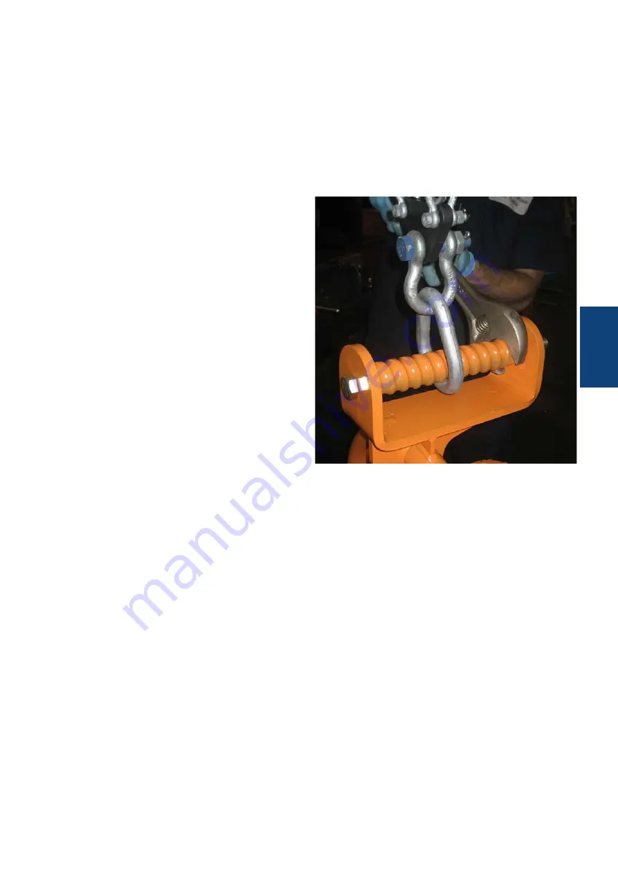
The tool can be leveled by turning the leveling screw atop the stationary hanger. Level the
spinner by turning the balance screw. Figure 4
Pipe Size Adjustment
The GraySpin Mark 40 will initially be set with the arm to cylinder connecting pin placed in
the rear position. This will accommodate most pipe sizes. If it is necessary to move the pin
to the front position, slowly activate the door valve until the pin is lined up past the front of
the top plate. This will occur with the doors
closed (cylinders extended). Disconnect
power source. Remove the locking socket
capscrew and pull the pin out. Rotate the
door to line up cylinder clevis with the front
pin position and replace pin locking cap
screw. Repeat for the opposite door. Reattach
power source.
WARNING: CHECK ALL SPRING HANGER ASSEMBLY
SHACKLES AND LOCK COTTER PINS FOR TIGHTNESS.
WARNING: CHECK SPRING SAFETY CABLES FOR
SOUNDNESS, (TWO REQUIRED). THE SPRING HANGER
ASSEMBLY IS NECESSARY TO ALLOW THE SPINNER TO RISE
AND FALL WITH THREADED TOOL JOINT MOVEMENTS.
WARNING: THE USE OF ONLY ONE BACKUP LINE CAN CAUSE
THE SPINNER TO SWING INTO THE OPERATOR OR FLOOR
PERSONNEL AND WILL CAUSE INJURY. USE TWO BACKUP
CABLES!
Figure 5
Summary of Contents for GraySpin Mark 40
Page 6: ...INTRODUCTION 6 INTRODUCTION ...
Page 10: ...SPECIFICATIONS 10 SPECIFICATIONS ...
Page 13: ...INSTALLATION 13 INSTALLATION ...
Page 16: ...OPERATION 16 OPERATIONS ...
Page 22: ...MAINTENANCE INSPECTION 22 MAINTENANCE INSPECTION ...
Page 28: ...MAINTENANCE INSPECTION 28 Lubrication Points Figure 18 ...
Page 29: ...ASSEMBLIES 29 ASSEMBLIES ...
Page 33: ...ASSEMBLIES 33 MOTOR MOUNT PLATE SUB ASSEMBLY 9G1084 3 Figure 26 ...
Page 38: ...ASSEMBLIES 38 Figure 30 RIGHT HAND DOOR ...
Page 40: ...ASSEMBLIES 40 Figure 31 LEFT HAND DOOR ...
Page 42: ...ASSEMBLIES 42 DRIVE ROLLER SUB ASSEMBLY 9G1081 30 Figure 32 BEARING CAP ASSEMBLY 9G1081 9 ...
Page 50: ...ASSEMBLIES 50 HYDRAULIC SCHEMATIC Figure 40 ...
Page 54: ...SPARE PARTS 54 SPARE PARTS ...
Page 56: ...INDEX 56 INDEX ...


