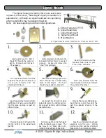
The Signal Heads provided in this kit are exact scale
replicas of the common, “Searchlight” signal (named after it’s
appearance). Although our signal heads are non-operating,
after-market LED’s may be installed if desired.
Note: We have supplied you with an extra signal head.
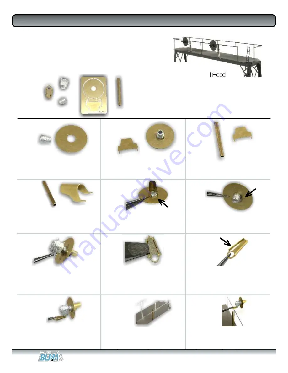
Locate parts A and C. Part C
should fit through the center of
part A. Remove burs from part
C if necessary.
A
E
D
B
C
A. Etched Target and Hood
B. Signal Head Body
C. Signal Head Insert
D. Signal Head Mount
E. Mounting Rod
1.
2.
3.
Bend the hood around the
provided brass pole to give
it the proper curvature.
It is imperative that the hood be
shaped to the proper curvature so it
will mount correctly onto the
assembly from step 2.
Insert the mounting pegs on the
hood through the corresponding
holes on the target. The hood
should wrap neatly around part C.
Once fully inserted, bend the
mounting tabs on the hood toward
the outside of the target.
6.
5.
4.
7.
8.
9.
12.
11.
10.
Glue the assembly from step 6 into
part B (part C’s narrow end should fit
into the large opening on part B).
Affix with glue.
Locate part D and bend its sides
perpendicular to the middle portion.
We suggest bending with toothless
pliers as shown.
Once both sides are folded down,
bend the tiny nub at the end of the
part the opposite direction of the
sides.
The small nub bent in figure 9 fits
into the bottom of the signal head
(part B).
Cut down part E so it is the height
of the handrail & glue in place. The
best way to cut brass tube is by
rolling it under a sharp hobby knife.
Glue the completed signal head
assembly onto the pole. Vertical
position and the number of signals
depends on the prototype modeled.
Our Signal Heads are also sold seperately in a three pack. BLMA #4000
Add a small amount of glue to the
A/C assembly from step 1 to secure it
in place. Locate and remove the
“hood” from etching A.
Signal Heads
Signal Heads
#4020 - Signal Bridge Instructions Page 6


