background image

25

A-QAMOS-4CI

Part N

o

: 5102.81

SAT-TV Transmodulator

DVB-S/ -S2 (8x QPSK/ 8PSK) 

→  

4x CI 

 DVB-C (8x QAM)

A

LINE

7.3.11 Menu ”NIT”

The NIT processing for all to a head end associated devices of the A-QAMOS- and QAMOS product group can be done in 2 ways: as 
an automatic or manual NIT processing. The simplest and by installation and support expense safest way is the automatic NIT proces-
sing. The precondition is that all to the head end associated above mentioned devices have a different IP address and an Ethernet 
switch must be connected to each other so that the data exchange can take place automatically. The NIT settings must be made here 
only in one of the above mentioned devices of the head end and after confirmation they are automatically included of all other devices.
The Ethernet connection among each other is not necessary for the manual NIT processing, but the settings must be made or maintai-
ned separately 

in each device

 of the head end, which means a much higher expense.

To start the NIT processing it is first necessary to put together the head end in the user interface. At first in the menu “Setup“ (see 
chapter 7.3.8) at the point “SBL head end“ the “Search“ button is to press. Alternatively, you can press the “Read“ button in the menu 
“Overview“ (see Section 7.3.1) under the item “SBL head end“ overview in the case of factory setting. First all devices of the 
A-QAMOS- and QAMOS product group are listed that are within the network. If there is no network connection between the mentioned 
devices (the case of manual NIT processing), here only this one device appears on which the settings are being implemented. The 
next step, all mentioned devices are selected, which should belong to the head end (in the case of the manual NIT processing the 
device itself) and the selection has to be confirmed with the “send“ button. In the case of an automatic NIT distribution now the data of 
all selected devices are exchanged. Further adjustments must be performed only in one device and be adopted by all the other auto-
matically.
In the case of a manual NIT processing this step must be implemented 

in each device

 of the head end. The data of the other devices 

must be taken manually in each device, as explained in subsequent chapters.

7.3.11.1 Automatic NIT processing

As explained above, all devices of the A-QAMOS- and QAMOS product group of the head end must be connected over an Ethernet 
switch for automatic NIT processing. The creation or editing of the NIT settings must only be done on one device of the head end and 
is then applied from all other devices automatically.
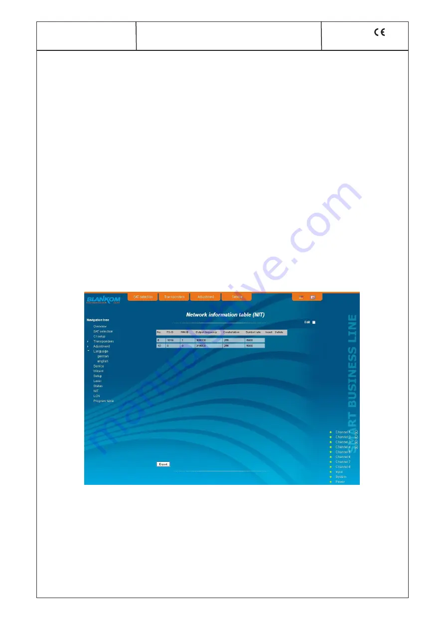
It presents the last created NIT table of the whole head end with continuous listing of the following parameters: transport stream ID, 
original network ID, output frequency in kHz, QAM constallation, symbol rate in kSps, insert and delete fields. A characteristic of the 
automatic NIT processing is that all channels of the devices are listed in frequency-ascending blue colored table cells. If the first time 
an NIT is created, a list appears with no table entries. The loading or update of the NIT is then in edit mode. By clicking the “Export“ 
button, the NIT of the head end is saved as a .xml-file on the PC. In the editing mode this settings can be changed.

By clicking the box “Edit“ in the top right of the user interface you can switch to edit mode and edit the NIT entries. With the “+“ 
button, an entry will be added. The settings of the last table entry are accepted and must be adjusted accordingly. With the “Delete“ 
button the table entry is removed. Also in this mode, you can save the NIT of the device with the “Export“ button as .xml-file on the PC. 
By clicking the “Import“ button, another NIT can be added, which was previously stored as a .xml file on the PC. In this way its easy 
possible to create a NIT of a system with multiple devices of the A-QAMOS and QAMOS product group. In the NIT processing all the 
selected table entries are included.
In the lower part of the GUI it appears additionally an overview of the settings for the NIT processing of all the channels of the head 
end. Here the NIT transmission per channel can be switched on or off easily and the network name and network ID can be changed. 
The settings are identical to the section “Transport stream processing” in the setup menu (see chapter 7.3.5).
If all settings have been made, with pressing the “send“ button this NIT is automatically stored in all other devices of the A-QAMOS 
and QAMOS product group of the head end.

Summary of Contents for A-QAMOS-4CI

Page 1: ...Professional Headend Solutions Device manual A QAMOS 4CI Part No 5102 81 SAT TV Transmodulator DVB S S2 8x QPSK 8PSK 4x CI DVB C 8x QAM...

Page 2: ...u Overview 10 7 3 2 Menu SAT selection 11 7 3 3 Menu CI setup 13 7 3 4 Menu Transponders 15 7 3 5 Menu Adjustment 16 7 3 6 Menu Language 17 7 3 7 Menu Service 18 7 3 8 Menu Setup 18 7 3 9 Menu Level 2...

Page 3: ...head end system A LINE which is conceived as a complete system for big and middle sized networks The A QAMOS 4CI converts digital satellite signals into QAM signals to transmit it in cable networks I...

Page 4: ...e is critical the device will no longer work or is forced to shut down off device is not ready for work CH 1 CH 8 green permanently on channel operates without error amber permanently on error warning...

Page 5: ...rrent e g by short circuit and or LNB overheated port is disabled temporarily off no tuner is locked on this input or port is deactivated only port IN OUT 6 4 2 Status LED at the output coupler Design...

Page 6: ...ts provided IP address within the network To that the address of the network port on the PC temporary must be adapted to the IP address of the A LINE SBL device subnet mask 255 255 255 0 IP address 19...

Page 7: ...feeds on the left If the system is operated with a Quattro LNB so you choose from the right side which satellite level contact with the corresponding input jack By pressing the OK button the correspo...

Page 8: ...r the selection all channels in this package will be listed in the middle list box In the upper part the television programs are listed and in the lower part the radio programs In the upper right list...

Page 9: ...ed by an online help Hovering the parameters by the mouse in the lower part of the site an orange colored text box appears with explanations for each parameter By setting in the Setup menu see chapter...

Page 10: ...lish top right 7 3 1 Menu Overview This page provides a status overview of the 8 channels If a channel is working without errors SYNC is displayed If errors occur you will see an Error display If the...

Page 11: ...sat jack 1 IN and 2 IN OUT Mode 1 selection not used input output LNB control selection on off remote supply off completely unicable DiSEqC selection on off Satellite 2 selection A B C D Tonburst sel...

Page 12: ...tested using the SUS 4481 F unicable module of the company Spaun For stable operation we recommend using a separate power supply for these modules Trouble free operation can not be gua ranteed when us...

Page 13: ...y the CA modules First you select the pathway of transport streams of the 4 channels The first selection point is channel 1 to be passed through module 1 channel 4 to be passed through module 4 Next y...

Page 14: ...is available for them The default is that the table editing SDT PMT EIT is performed Thereby the CA descriptor 0x09 will be replaced in the PMT through the user defined descriptor 0xFE If this descrip...

Page 15: ...on the selected channel are listed with their name and service ID To make changes you must first select the desired channel This is done either by clicking the appropriate selector outside right next...

Page 16: ...nnel frequency 2 Output frequency selection from channel table input in kHz 2 Output level offset display of the level offset 3 QAM constellation selection 16 32 64 128 256 QAM Symbol rate input in kS...

Page 17: ...part of the overview there is the selector of the filter activation at the top In the second box Filter mode you choose whether the selected channels are blocked or allowed to pass In the box Informat...

Page 18: ...the BLANKOM service hotline and the service email address In addition the implemented operating instructions may be downloaded or viewed as PDF If there is an in ternet connection the BLANKOM homepag...

Page 19: ...to the right of the user interface Optimization for low speed data connectivity By clicking the box the data volume of the browser pages is greatly reduced So it is possible to adjust the device if t...

Page 20: ...e g other satellite assignments Software Update By clicking the Load button the internal software components can always be brought up to date Pressing the button View logbook leads to an overview in w...

Page 21: ...igned The address range must match the address range according to IP address and subnet mask of the server and should not be too small The default is the area 192 168 1 1 to 192 168 1 99 Additionally...

Page 22: ...they should trigger traps There are three ways to configure a trap without parameters e g fan on off with a freely selectable parameters for a medium priority with a selectable parameter from a list...

Page 23: ...kilobytes To upload or change the transport stream file click the button Upload File In the follo wing dialog you select a file and can optionally specify a text description for this file Note that n...

Page 24: ...teps The three lower buttons are used to simplify the offset level setting if you want to perform same adjusting for all 8 channels With the left button the offset for all 8 channels is increased by 0...

Page 25: ...data of the other devices must be taken manually in each device as explained in subsequent chapters 7 3 11 1 Automatic NIT processing As explained above all devices of the A QAMOS and QAMOS product gr...

Page 26: ...here appear the added tables in white color After the appropriate selection of channels of the NIT and any change in the network name or network ID the NIT of this device is stored and transferred by...

Page 27: ...separated for HD and SD programs all services are still provided with the number 0 You can now assign the LCN for the selected program automatically by pressing the OK button in the right box automati...

Page 28: ...e it will restart the device and all stored values are adjusted If the device is to be reset to factory settings the reset button must be pressed so long to keep up until the POWER and SYSTEM LED wil...

Page 29: ...typing java version followed by Enter Result is either an error message if Java is not installed or the version information of the existing Java installation 2 Installing the necessary software FFmpe...

Page 30: ...erform post processing you have to link the path to tsmux exe in the converter Then click the button path to post processing pictured in green and click it there by their own folder structure to the p...

Page 31: ...ll Pakete komprimieren and Vermeidung von Continue Count Fehlern remain inactive 9 4 Error prevention 1 If you want to create HD video from SD material so it is to be reckoned with qualitative degrada...

Page 32: ...CONTROL A QAMOS 4CI ASI TSIN IN OUT CONTROL A QAMOS 4CI F F F F F A QAMOS 4CI A QAMOS 4CI A QAMOS 4CI 192 168 1 101 192 168 1 102 192 168 1 103 Feed SAT IF Feed SAT IF Feed SAT IF Output QAM 82 dB V S...

Page 33: ...21 7 cascadable Operating voltage 5 V Multi Service decryption 48 services max Input data rate max 75 Mbps acc adjustment symbol rate CAM QAM modulator Input data rate max 75 Mbps acc adjustment symbo...

Page 34: ...rd Definition Television SI Service Information SNMP Single Network Management Protocol SPTS Single Program Transport Stream TS Transport Stream TV Television URL Uniform Resource Locator WAN Wide Are...

Page 35: ...or at your option any later version You should have received a copy of the GNU General Public License along with Foobar If not see http www gnu org licenses The source code is available upon request...

Page 36: ...or the approximation of legislation of the member states Electromagnetic compatibility 2004 108 EC The following standards are met DIN EN 50083 2 2007 04 EN 50083 2 2006 06 Low voltage guideline 2006...

Reviews: