1301-C00 page 6/56
2.3 Leveling
Sufficient parallel machined bearing plates or chock blocks
should be placed beneath the base along the sides and ends,
to distribute the load evenly. It is essential that they are leveled
before the base is placed in position. Obtain an accurate
condition of level lengthwise and crosswise.
2.4 Grouting
The anchor bolts are used for hold down only. The grouting
resists side thrust, end thrust and compensates for the
irregularities between the foundation and the base, thus
preventing the pump unit from shifting.
Use only a “high strength”, “non-shrinking”, “non-expanding”,
grouting mixture.
Allow the grouting to set before tightening the anchor bolts.
After tightening, check the coupling alignment to make sure it
has not changed. Realign as required per the instructions in
section 2.5.
NOTICE:
Do not connect piping to the pump until the grouting is
sufficiently cured.
2.5 Coupling Alignment
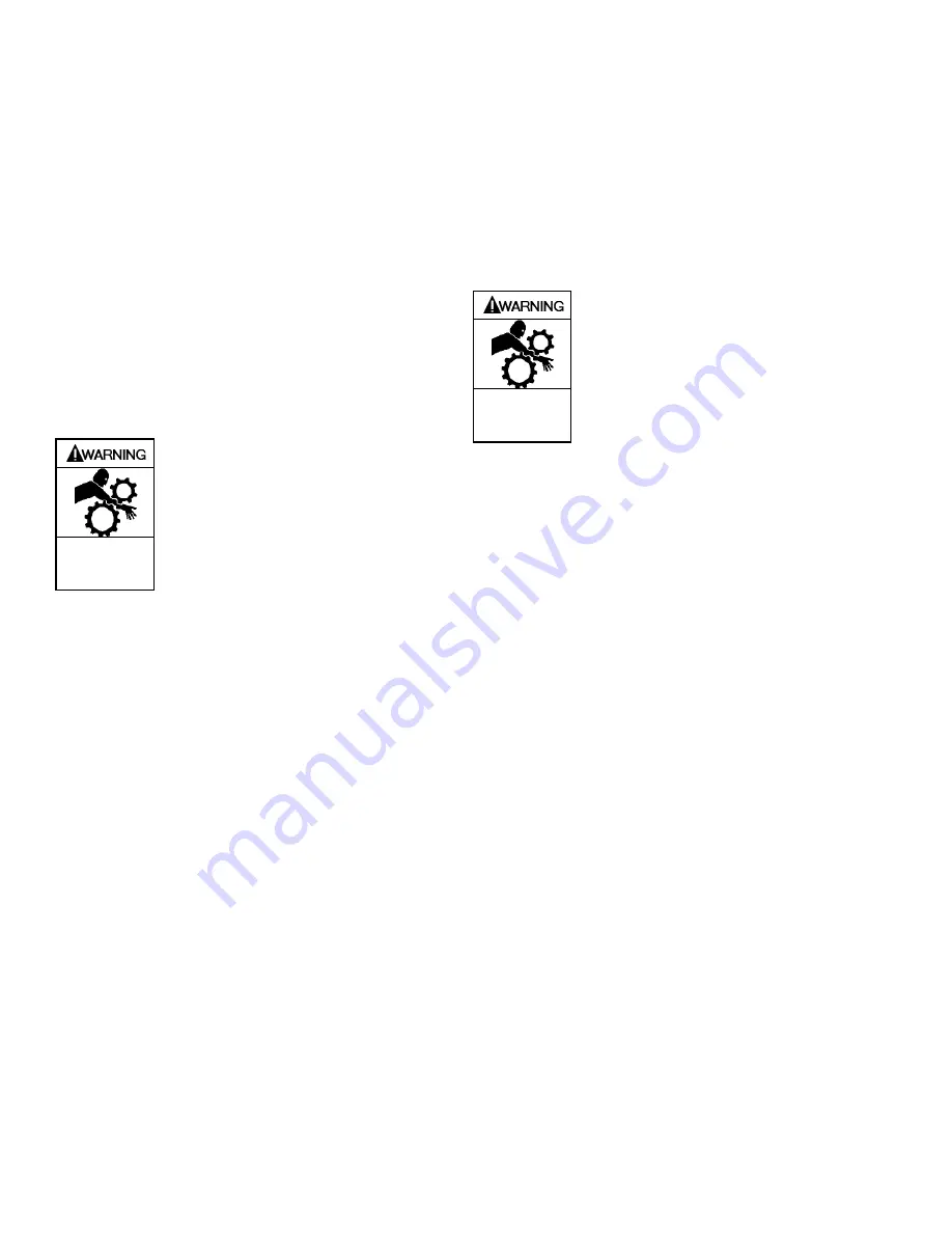
Be sure to lock-out electrical power to
the driver before performing alignment.
Failure to lock-out power could result in
serious injury.
Hazardous
machinery can
cause serious
personal injury.
NOTICE:
Check the driver direction of rotation BEFORE coupling it
to the pump. The direction of pump rotation is indicated
on the front surface of the casing. Improper direction of
rotation will damage the pump.
Good service life of the pump and driver depends upon good
alignment through the flexible coupling. If the electric motor
was mounted at the factory, the pump and motor were in
alignment when shipped.
Coupling Information:
Pump and motor coupling should be the flexible type.
Select a spacer coupling for pumps that do not use a motor
adapter.
Shaft gaps are as follows for non C frame pumps:
Frame SD: 3.9 in. (100 mm)
Frame S and Frame A: 3.5 in. (89 mm)
Frame M: 5.0 – 7.0 in. (127 – 178 mm)
Select a non-spacer or semi-spacer type for use with a motor
adapter, depending on shaft gap.
If a motor adapter is used, check to see if the selected
coupling will fit inside the adapter.
There should be at least 0.12 in. (3 mm) gap between the
pump and motor shafts on pumps with motor adapters.
When aligning the shafts, the coupling should be
disconnected and the coupling halves brought into
alignment.
Alignment Checks:
Cold alignment should be checked before and after
baseplate is grouted.
Piping should be connected to the pump prior to cold
alignment after the baseplate is grouted.
Final or hot alignment is to be done after the pump and
driver have operated for a sufficient length of time to attain
operating temperature.
Periodic checks of alignment should be made to ensure
smooth, continuous operation.
Any changes to process conditions warrant an alignment
check.
Once alignment is completed, the
coupling guard must be installed to
prevent injury. Never operate pump
without coupling guard properly
installed.
Do not operate
without guard
in place
NOTICE:
The alignment between the driver and pump should be
inspected after installation to ensure that transportation
or other handling has not caused misalignment of the
unit.
Alignment must not be attempted until the base is in position
and the mounting and flange bolts have been tightened.
Alignment should be performed after the pump and driver are
at operating temperature.
Alignment Method:
There are numerous devices and methods for accomplishing
proper coupling alignment. Specific alignment method is the
customer’s choice. If information is required for the double dial
indicator method, the Blackmer factory can provide details.
Also, information is available in the Hydraulic Institute
Standards. Both angular and parallel misalignments must be
corrected.
Alignment Criteria:
The unit is in complete alignment when offset and angular
Total Indicated Runout (TIR) measure less than .005 in. (.13
mm). Offset alignment is measured on the rim of the coupling
and angular alignment is measured on the face of the
coupling. If either reading exceeds these values, corrections
must be made.
Summary of Contents for SYSTEM ONE
Page 27: ...1301 C00 page 26 56 8 2 Pump Assembly Parts List Frame S Horizontal 6 1 ...
Page 28: ...1301 C00 page 27 56 8 3 Pump Assembly Parts List Frame S Horizontal 8 ...
Page 29: ...1301 C00 page 28 56 8 4 Pump Assembly Parts List Frame A and IPP Frame A ...
Page 30: ...1301 C00 page 29 56 8 5 Pump Assembly Parts List LD17 and IPP LD17 ...
Page 31: ...1301 C00 page 30 56 8 6 Pump Assembly Parts List Vortex Frame A and IPP Vortex Frame A ...
Page 32: ...1301 C00 page 31 56 8 7 Pump Assembly Parts List Vortex LD17 and IPP Vortex LD17 ...
Page 33: ...1301 C00 page 32 56 8 8 Pump Assembly Parts List Frame M ...
Page 55: ...1301 C00 Page 54 56 notes ...
Page 56: ...1301 C00 Page 55 56 notes ...


