1301-C00 page 12/56
4. Check Rotating Element.
Turn the shaft by hand several times to ascertain a free
rotating element. There will be a degree of resistance due
to the bearings and the mechanical seal. If any rubbing
noise occurs, do not attempt to operate the pump. Re-
adjust the impeller clearance as outlined in section 4.3
and 4.4 and reset the mechanical seal per its instructions.
5. Check
Lubrication.
Check the pump, motor and coupling to make certain they
are properly lubricated. See section 2.8 for pump
lubrication information.
6. Check Radial Bearing
Labyrinth Seal (Frames A and LD17 only). If the frame
adapter is rotated, relocate the stator portion of the
labyrinth so that the oil drain groove is located at the 6
o’clock position. See Section 4.2.
3.3 Auxiliaries Startup
Prior to priming and starting the pump, auxiliary components
on the unit must be turned on where applicable. The pump
motor must not be started until all the auxiliary systems are in
full operation.
Bearing Frame Cooling
If applicable, turn on the water to the cooling coil in the bottom
of the oil sump. For proper flow, see section 2.9.
Mechanical Seal
If applicable, turn on the flush, quench or forced barrier fluid to
the mechanical seal. Adjust flow and pressure as
recommended by the installation instructions provided with the
sealing device. If environmental controls include a heat
exchanger, turn on the heating/cooling fluid.
Seal Chamber Jacket
If applicable, turn on the water to the cooling jacket mounted
on the seal chamber. For proper flow, see section 2.9.
3.4 Priming
The pump is now ready to be primed.
1. Close the pump discharge valve.
2. Open the pump suction valve.
Never operate the pump dry. It is
important that the pump never be
subjected to thermal shock. The liquid
must be allowed to enter the pump
casing slowly. The pump should never
be started until all parts have been
gradually brought to the ultimate
intended pump temperature.
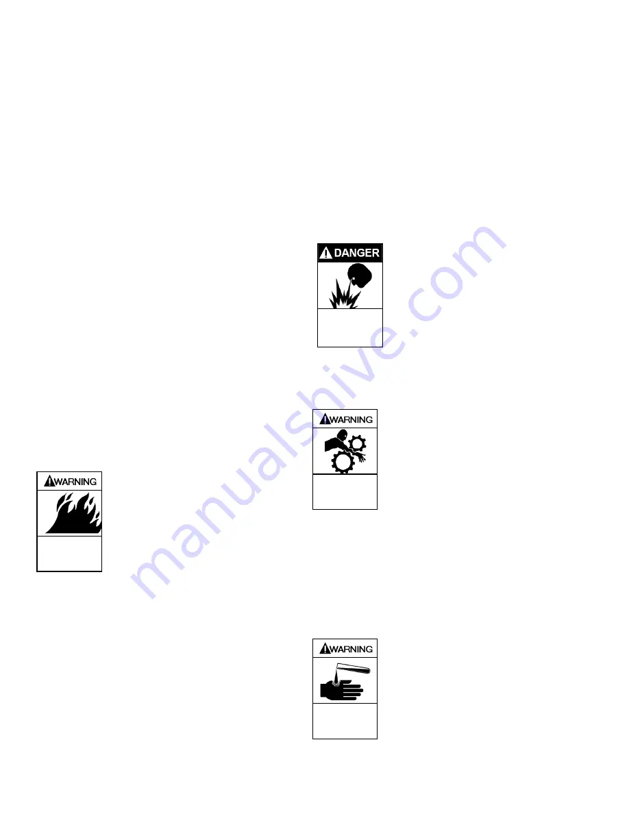
Hazardous fluids can
cause fire, serious
personal injury or
property damage.
3. After priming ensure that all vent and/or ejector
connections are closed.
3.5 Startup
NOTICE:
Prior to startup, and while pump is still locked-out to
prevent accidental startup
,
ensure the shaft turns freely
by hand! (clockwise when facing the coupling end)
Fully open the suction valve. Start the pump with the discharge
valve approximately 20% open, then open gradually until
design flow point is reached. The discharge valve should be
adjusted to achieve proper process flow with the pump
operating as close to the BEP as possible. Make certain the
suction line is not throttled nor restricted in any way during
operation.
3.6 Pump Performance
After the pump is running, check to see that it is running at, or
close to, the operating point on the pump performance curve.
If the pump is delivering too great a volume, or overloading the
motor, throttle the discharge valve. It may be necessary to add
a restriction orifice at the pump discharge to control the pump
capacity.
Check and monitor all the flows and pressures to the auxiliary
components. Adjust the flows and pressures accordingly.
Check the mechanical seal for leakage. Check all connections
for possible leaks and tighten where necessary.
After the pump has run for about one hour and is at full
operating temperature, shut it down, lockout the power, and
turn (in the direction of the rotation arrow) the shaft by hand to
determine that the rotating element is not binding and the
impeller is not rubbing. Shaft alignment should be checked.
See section 2.5 for coupling alignment.
Never operate the pump below minimum
rated flow and/or with the discharge
valve closed. These operating
conditions could cause extreme
temperature rise in the pump and an
explosive hazard. Also, premature
failure can result due to high radial
loads and vibration on the pump shaft.
Explosive fluids will
cause severe
personal injury
death or major
property damage.
3.7 Shutdown
When shutting down the pump, proceed as follows:
1. Turn off the driver and de-energize power. Be sure motor
is locked out before attempting to work on the pump.
Lock-out driver to prevent accidental
start-up and physical injury..
Hazardous
machinery can
cause serious
personal injury.
2. Close the discharge valve.
3. Close the suction valve.
4. Drain the pump casing.
5. Turn off all auxiliary components in the reverse sequence
from startup.
6. In cold weather, the entire pump, including all auxiliary
components, should be completely drained to prevent
damage from freezing.
Tagging valves should be standard practice by user.
When handling hazardous and/or toxic
fluids, use personal protection
equipment to avoid personal injury.
Pumpage must be handled and
disposed of in accordance with
applicable environmental regulations.
. Hazardous or
toxic fluids can
cause serious
injury.
Summary of Contents for SYSTEM ONE
Page 27: ...1301 C00 page 26 56 8 2 Pump Assembly Parts List Frame S Horizontal 6 1 ...
Page 28: ...1301 C00 page 27 56 8 3 Pump Assembly Parts List Frame S Horizontal 8 ...
Page 29: ...1301 C00 page 28 56 8 4 Pump Assembly Parts List Frame A and IPP Frame A ...
Page 30: ...1301 C00 page 29 56 8 5 Pump Assembly Parts List LD17 and IPP LD17 ...
Page 31: ...1301 C00 page 30 56 8 6 Pump Assembly Parts List Vortex Frame A and IPP Vortex Frame A ...
Page 32: ...1301 C00 page 31 56 8 7 Pump Assembly Parts List Vortex LD17 and IPP Vortex LD17 ...
Page 33: ...1301 C00 page 32 56 8 8 Pump Assembly Parts List Frame M ...
Page 55: ...1301 C00 Page 54 56 notes ...
Page 56: ...1301 C00 Page 55 56 notes ...


