


USB560v2-IG-01
18
XBlackhawk USB560v2 System Trace Emulator
3.3 Hardware
The following section describes the BH560v2 hardware installation process.
CAUTION:
Be very careful with the target cable connectors. Connect them with care; don’t force
them into position or damage may result.
WARNING:
Do not connect or disconnect the emulator cable while the target system is powered.
Installing the BH560v2 hardware requires these two steps.
•
Configuring the emulator cable assembly with pin converters (if necessary)
•
Installing the host PC connection (USB)
3.3.1 Configuring the Emulator Cable Assembly
The BH560v2 cable assembly requires no changes for use with MIPI60 target connections. For
other target connections, such as TI 14-pin JTAG, use the supplied pin converters (see Figure 25
and refer to section 2.5).
After you determine the correct pin converter necessary for your target board, or not needed, the
cable assembly can be put together following these easy steps.
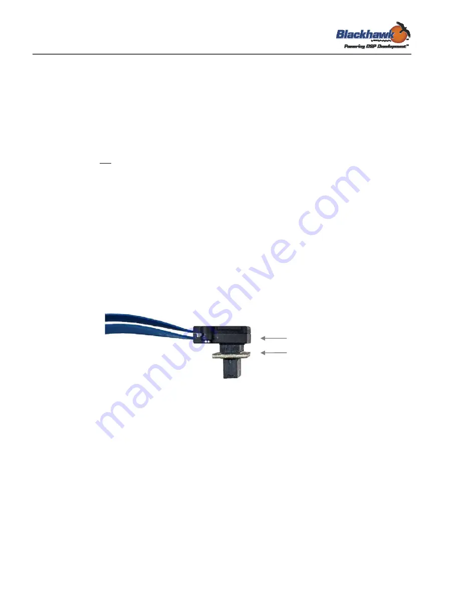
Attach the pin converter to the JTAG cable by pressing the connectors together with the correct
orientation making sure you don’t force them. The result is shown in Figure 25.
JTAG Cable
Pin Converter
Figure 25 - JTAG Cable + Pin Converter
3.3.2 USB Cable Assembly
Attach the USB cable “A” connector to an available USB port on the PC or USB hub. Then
attach the mini-B connector to the emulator’s mini-B port (see Figure 3).
Once both connections are made, the emulator will power-on.