


21
CHAPTER 3: Installation
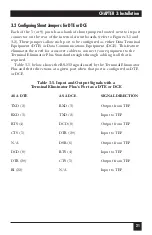
3.2 Configuring Shunt Jumpers for DTE or DCE
Each of the 5 (or 9) ports has a bank of shunt jumpers located next to its port
connector on the rear of the internal circuit boards (refer to Figures 3-1 and
3-2). These jumpers allow each port to be configured as either Data Terminal
Equipment (DTE) or Data Communications Equipment (DCE). This feature
eliminates the need for crossover cables to connect your equipment to the
Terminal Eliminator Plus. Standard straight-through cabling is all that is
required.
Table 3-5, below, shows the RS-232 signals used by the Terminal Eliminator
Plus and their directions at a given port when that port is configured as DTE
or DCE.
Table 3-5. Input and Output Signals with a
Terminal Eliminator Plus’s Port as a DTE or DCE
AS A DTE
AS A DCE
SIGNAL DIRECTION
TXD (2)
RXD (3)
Output from TEP
RXD (3)
TXD (2)
Input to TEP
RTS (4)
DCD (8)
Output from TEP
CTS (5)
DTR (20)
Input to TEP
N/A
DSR (6)
Output from TEP
DCD (8)
RTS (4)
Input to TEP
DTR (20)
CTS (5)
Output from TEP
RI (22)
N/A
Input to TEP


