


2.1.
WHEN THE SERVER IS UP AND RUNNING
7
b) RAS-PutIn utilities
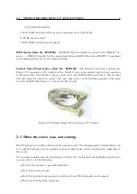
3. RAS-PutIn keyboard video mouse connection cable (Sub D 25)
4. NULL modem cable
5. RAS-PutIn external power supply
IPMI Option (Item No. 8400300)
The IPMI Option consists of a serial cable (SUB-D 9 fe-
male
←→
SUB-D 9 female) for the connection between RAS-PutIn and an IPMI V1.5 compliant
serial management port on the remote system.
Internal Reset/Power Option (Item No: 8400100)
The internal reset/power option (see
Figure
) consists of a PC bracket with a Sub-D 9 jack on the outside and 4x2 pin connector
in the inner side. The Sub-D 9 jack is connected to the RAS-PutIn Serial Port 2. The internal
4x2 pin connector allows to connect the reset and power on/off switching signals of the main
board to RAS-PutIn. Figure
shows the PC bracket.
Figure 2.2: Internal Reset/Power Option - PC bracket
2.1 When the server is up and running
RAS-PutIn gives you full control over the remote server. The Management Console allows you
to access the remote server’s graphics, keyboard and mouse and to send special commands to
the server.
You can also perform periodic maintenance of the server. Using the Console Redirection Service,
you are able to do the following:
Reboot the system (a graceful shutdown).
Watch the boot process.
Boot the system from a separate partition to load the diagnostic environment.
Run special diagnostic programs.
Summary of Contents for RAS-PutIn
Page 1: ...RAS PutIn Installation and User Guide Based on Firmware 03 02 07 ...
Page 4: ...iv ...
Page 8: ...viii Contents ...
Page 12: ...xii List of Tables ...
Page 30: ...18 CHAPTER 4 CONFIGURATION ...
Page 76: ...64 CHAPTER 5 USAGE ...
Page 80: ...68 APPENDIX A GLOSSARY ...
Page 82: ...70 APPENDIX B RAS PUTIN VIDEO MODES ...
Page 88: ...76 APPENDIX D PIN ASSIGNMENTS ...
Page 92: ...80 APPENDIX F SPECIFICATIONS ...


