


5
CONTENTS
Contents
Chapter
Page
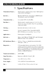
1. Specifications ............................................................................................................6
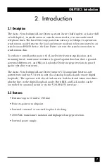
2. Introduction ..............................................................................................................7
2.1
Description ....................................................................................................7
2.2
Features ..........................................................................................................7
3. Configuration ............................................................................................................8
3.1
Configuration Switches ................................................................................8
3.2
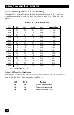
Configuration Switch Set S1 ........................................................................9
3.3
Configuration Switch Set S2 ......................................................................11
3.4
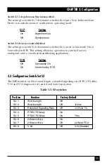
Configuration Switch Set S3 ......................................................................13
4. Installation ..............................................................................................................16
4.1
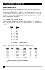
Two-Wire Installation ..................................................................................16
4.1.1 Two-Wire Cable Connection via RJ-45 ................................................17
4.2
Four-Wire Installation ................................................................................18
4.2.1 Four-Wire Cable Connection via RJ-45 ..............................................18
4.3
Four-Wire, Multipoint Installation ............................................................19
4.3.1 Multipoint Twisted-Pair Connection ..................................................20
4.4
RS-232 Connection ......................................................................................20
5. Operation ................................................................................................................21
5.1
LED Status Monitors....................................................................................21
5.1.1 The Power, TX, and RX Indicators ....................................................21
5.1.2 The RTS and CD Indicators ................................................................21
5.1.3 The Test Indicator ................................................................................22
5.1.4 The Error Indicators ............................................................................22
5.2
Anti-Streaming Error Indicator ..................................................................22
5.3
Power-Up ......................................................................................................22
5.4
V.54 Test Modes ..........................................................................................23
5.4.1 Local Analog Loopback (LAL)............................................................23
5.4.2 Remote Digital Loopback (RDL) ........................................................24
5.4.3 Using the V.52 BER Test Independently ............................................24
5.5
Power-Down ................................................................................................25
Appendix. Cable Recommendations ..........................................................................26