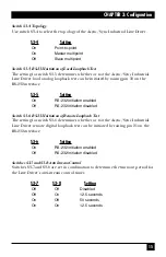
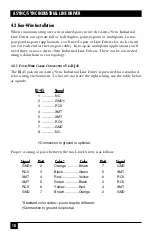
Black Box ME500A Manual Download Page 24

23

CHAPTER 5: Operation
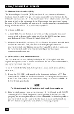
5.4 V.54 Test Modes

The Async/Sync Industrial Line Driver offers two V.54 test modes to evaluate the
condition of the modems and the communication link. These tests can be
activated physically from the front panel or via the RS-232 interface.

NOTE

V.54 test modes are available for point-to-point applications only.

5.4.1 L

OCAL

A

NALOG

L

OOPBACK

(LAL)

The Local Analog Loopback (LAL) test checks the operation of the local
Async/Sync Industrial Line Driver and is performed separately on each unit. In
this test mode, any data sent to the local Line Driver will be echoed back
(returned) to the user device. For example, characters typed on the keyboard of a
terminal will appear on the terminal screen.

To perform a LAL test:

1. Activate LAL. You can do this in one of two ways: by moving the front-panel

toggle switch to Local or by raising pin 18 on the RS-232 interface (Make sure
DIP-switch S2-6 is OFF, and DIP-switch S3-5 is ON). Once LAL is activated, the
Line Driver’s transmit output is connected to its own receiver. The Test LED
should be lit.

2. Verify that the data terminal equipment is operating properly and can be used

for a test. If a fault is indicated, call Technical Support.

3. Perform a BER (bit error rate) or 511/511E test on each Line Driver. If the

BER-test equipment indicates no faults, but the data terminal indicates a fault,
follow the manufacturer’s checkout procedures for the data terminal. Also,
check the RS-232 interface cable between the terminal and the Line Driver.

Summary of Contents for ME500A

Page 1: ...s a day 7 days a week Call 724 746 5500 or fax 724 746 0746 Mailing address Black Box Corporation 1000 Park Drive Lawrence PA 15055 1018 Web site www blackbox com E mail info blackbox com SEPTEMBER 19...

Page 2: ...KS TRADEMARKS USED IN THIS MANUAL AT T is a registered trademark of American Telephone and Telegraph Company Any other trademarks used in this manual are acknowledged to be the property of the tradema...

Page 3: ...n the equipment is operated in a commercial environment Operation of this equipment in a residential area is likely to cause interference in which case the user at his own expense will be required to...

Page 4: ...ato el ctrico debe ser montado a la pared o al techo s lo como sea recomendado por el fabricante 8 Servicio El usuario no debe intentar dar servicio al equipo el ctrico m s all a lo descrito en las in...

Page 5: ...de existir una antena externa deber ser localizada lejos de las lineas de energia 16 El cable de corriente deber ser desconectado del cuando el equipo no sea usado por un largo periodo de tiempo 17 C...

Page 6: ...2 1 Four Wire Cable Connection via RJ 45 18 4 3 Four Wire Multipoint Installation 19 4 3 1 Multipoint Twisted Pair Connection 20 4 4 RS 232 Connection 20 5 Operation 21 5 1 LED Status Monitors 21 5 1...

Page 7: ...RTS RTS CTS delay set to no delay 7 ms or 53 ms Applications Point to point or multipoint Indicators Mono color LEDs for TX RX RTS and CD Single LEDs for Power Test and Error RTS Anti Stream Timer 12...

Page 8: ...transformer isolation to guard against data loss due to ground potential differences and Silicon Avalanche Diode surge protection to guard against data line transients The Async Sync Industrial Line...

Page 9: ...r configuration The configuration switches allow you to select data rates clocking methods V 52 and V 54 tests word lengths extended signaling rates async or sync mode 2 or 4 wire operation anti strea...

Page 10: ...method The default settings are shown in the table below Table 3 1 S1 switches Position Function Factory Default S1 1 Data Rate On S1 2 Data Rate Off 9600 bps S1 3 Data Rate Off S1 4 Data Rate On S1 5...

Page 11: ...Off 2 4 Off Off On On Off 3 6 On On Off On Off 4 8 Off On Off On Off 7 2 On Off Off On Off 9 6 Off Off Off On Off 14 4 Off On Off On On 16 On On On Off Off 19 2 Off On On Off Off 28 8 Off Off Off On...

Page 12: ...allows for operation in switched carrier multipoint and or hardware handshaking applications S1 8 Setting Off Constantly On On Controlled by RTS 3 3 Configuration Switch Set S2 The DIP switches on S2...

Page 13: ...ariance from a given frequency level the Line Driver will tolerate S2 3 Setting Off 2 5 to 1 On 2 5 to 2 3 Switches S2 4 and S2 5 RTS CTS Delay The combined settings for switches S2 4 and S2 5 determi...

Page 14: ...control timing mode topology local loopback enable remote loopback enable and input impedance levels for the Async Sync Industrial Line Driver Factory default positions are shown in the table below Ta...

Page 15: ...n On 130 ohms On Off 200 ohms Off On 320 ohms Off Off High impedance minimum 2k ohms Table 3 5 Speed Selection Cable Gauge Data Rates kbps 1 2 1 8 2 4 3 6 4 8 7 2 9 6 14 4 19 AWG 0 9 mm 320 320 200 20...

Page 16: ...Setting On RS 232 initiation enabled Off RS 232 initiation disabled Switch S3 6 RS 232 Initiation of Remote Loopback Test The setting for switch S3 6 determines whether or not the Async Sync Industria...

Page 17: ...nnection Figure 4 1 shows the location of the RJ 45 jack on the Line Driver s rear panel Connect the wire to each Line Driver as described in the instructions that follow the illustration Figure 4 1 T...

Page 18: ...use the table below as a guide RJ 45 Signal 1 NC 2 GND 3 RCV 4 XMT 5 XMT 6 RCV 7 GND 8 NC Connection to ground is optional Proper wiring of pairs between the two Line Drivers is as follows Signal Pin...

Page 19: ...ing a daisychain or star topology 4 2 1 FOUR WIRE CABLE CONNECTION VIA RJ 45 The RJ 45 jack on an Async Sync Industrial Line Driver is prewired for a standard telco wiring environment To be sure you h...

Page 20: ...master Async Sync Industrial Line Driver transmits continually Initiation of two way communication is RTS controlled by each slave Async Sync Industrial Line Driver To facilitate multipoint communica...

Page 21: ...to wire the one pair and two pair cables properly for a star topology Note that the ground connection is not needed Host First Slave Second Slave XMT RCV RCV XMT RCV RCV RCV XMT XMT RCV XMT XMT Host...

Page 22: ...INDICATORS The Power LED lights green to signal that power is present The TX and RX indicators blink green with data activity Off indicates a low RS 232 logic level solid green indicates a high RS 23...

Page 23: ...timer begins to count when the DTE raises RTS If the time period that RTS remains high exceeds the preset time out period the anti stream circuit will force RTS low The Error LED will light red indica...

Page 24: ...on the keyboard of a terminal will appear on the terminal screen To perform a LAL test 1 Activate LAL You can do this in one of two ways by moving the front panel toggle switch to Local or by raising...

Page 25: ...h the twisted pair line between the Line Drivers Test the twisted pair line for proper connections and continuity 5 4 3 USING THE V 52 BER TEST INDEPENDENTLY The V 52 BER test can be used independentl...

Page 26: ...25 CHAPTER 5 Operation 5 5 Power Down To turn off the Async Sync Industrial Line Driver simply unplug the AC power cord from the wall There is no power switch...

Page 27: ...to reduce the potential difficulties in the field make sure that the cable being used has similar or better characteristics lower capacitance or lower resistance Table A 1 Distance in miles km Data Ra...

Page 28: ...e however distances may vary Resistance will also affect distance but not functionality Wire should be 26 AWG 0 4 mm or larger smaller AWG This Line Driver is designed to withstand normal environmenta...

Page 29: ...1000 Park Drive Lawrence PA 15055 1018 724 746 5500 Fax 724 746 0746 Copyright 1999 Black Box Corporation All rights reserved...

Reviews: