


22
ASYNC/SYNC INDUSTRIAL LINE DRIVER
5.1.3 T
HE
T
EST
I
NDICATOR
The yellow Test LED indicates that V.52 or V.54 tests are running.
5.1.4 T
HE
E
RROR
I
NDICATORS
The Error indicator LED has two functions:
• When the Async/Sync Industrial Line Driver is in test mode (green Test LED is
lit), the Error LED glows red when bit errors occur.
• When not in test mode (green Test LED is off), the Error LED indicates an RTS
streaming condition. (See
Section 5.2
for information on the anti-streaming
circuitry.)
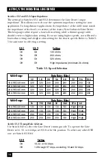
5.2 Anti-Streaming Error Indicator
When not in test mode (green Test LED is off), the Error LED indicates a
streaming error. When the Async/Sync Industrial Line Driver’s anti-streaming
circuitry is enabled, the RTS signal from the DTE is timer controlled. The timer
begins to count when the DTE raises RTS. If the time period that RTS remains
high exceeds the preset time-out period, the anti-stream circuit will force RTS low.
The Error LED will light red, indicating a streaming condition (RTS continually
on). This prevents a malfunctioning terminal from tying up a computer port in a
multi-drop or polling environment. When the DTE drops RTS, the anti-streaming
timer is automatically reset and the Error LED turns off. The time-out period is
DIP-switch selectable for 12.5 or 50 seconds.
5.3 Power-Up
Apply AC power to the Line Driver by plugging the separate AC power cable first
into the Line Driver’s rear panel and then into an acceptable AC power outlet. The
Remote/Normal/Local switch should be set to Normal. When the local and
remote Async/Sync Industrial Line Drivers are powered up and passing data
normally, these LED conditions will exist:
• TX and RX = flashing on and off
• RTS and CD = green
• TEST = off