background image

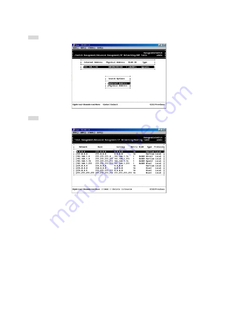
Search for ARP Table Entries

Step 4:  Press <S> to search a static entry. You can search by Internet address or physical address.

ROUTING TABLE

Step 1:  Move to highlight [Routing Table] from [IP Networking] and press <Enter>. The screen shows the Routing 
Table allows you to view, add, delete or search a particular routing path.

Summary of Contents for LBG1000A

Page 1: ... support Call 724 746 5500 or fax 724 746 0746 Technical support and fax orders 24 hours a day 7 days a week Phone orders 24 hours 7 A M Monday to midnight Friday Saturday 8 to 4 Eastern Mail order Black Box Corporation 1000 Park Drive Lawrence PA 15055 1018 Web site http www blackbox com E mail info blackbox ...

Page 2: ...eguridad y operación deberán ser leídas antes de que el aparato eléctrico sea operado 2 Las instrucciones de seguridad y operación deberán ser guardadas para referencia futura 3 Todas las advertencias en el aparato eléctrico y en sus instrucciones de operación deben ser respetadas 4 Todas las instrucciones de operación y uso deben ser seguidas 5 El aparato eléctrico no deberá ser usado cerca del a...

Page 3: ...ntilación 18 Servicio por personal calificado deberá ser provisto cuando A El cable de poder o el contacto ha sido dañado u B Objectos han caído o líquido ha sido derramado dentro del aparato o C El aparato ha sido expuesto a la lluvia o D El aparato parece no operar normalmente o muestra un cambio en su desempeño o 3 ...

Page 4: ...LX ports For the two Gigabit ports it allows options of fiber type and wavelength at user s discretion This switch brings a simple answer to today s complicated networking environments To get the most out of this manual you should have an understanding of Ethernet networking concepts In this manual you will find Features on the switch Illustrative LED functions Installation instructions Management...

Page 5: ...External SNMP based network management application 23 INSTALLATION 24 SELECTING A SITE FOR THE SWITCH 24 CONNECTING TO POWER 25 Power on Self test POST 26 CONNECTING TO YOUR NETWORK 27 Cable Type Length 27 Cabling 28 SWITCH MANAGEMENT 29 MANAGEMENT ACCESS OVERVIEW 30 ADMINISTRATION CONSOLE 31 Direct Access 31 Modem Access 32 WEB MANAGEMENT 33 Netscape Navigator 33 Internet Explorer 33 SNMP BASED N...

Page 6: ...art with Selection Menu 97 LAN Port Configuration 99 Console Port Configuration 101 PERFORMING ADVANCED SETUP ACTIVITIES 103 Start with Selection Menu 103 MAC Address Management 104 IP Networking 108 Per Port Statistics 117 Port Priority 118 Bridging 119 Static MAC Filter 120 IP Multicast Group 123 VLAN Perspective 124 Spanning Tree Perspective 128 SNMP 131 Other Protocols 133 Port Trunking 134 Po...

Page 7: ...s When you unpack the product package you shall find the items listed below Please inspect the contents and report any apparent damage or missing items immediately to your authorized reseller This Manageable Switch User s Manual AC power cord RS232 cable Rackmount brackets with screws ...

Page 8: ......

Page 9: ... 8M bit memory buffer Provides one uplink button for port 24X Front panel reset button Front panel port status LEDs Standard 19 rackmount size one unit height Management Support VLAN Port based VLAN up to eight groups 802 1Q tagged VLAN TRUNKING MAC based Trunking up to four groups with a maximum of four ports each group Load sharing based on source and destination MAC addresses PORT SECURITY Limi...

Page 10: ...anning Tree 802 1p Q GARP GVRP Routing RIP RIP 2 DHCP Relay ICMP Router Discovery Message IP Multicast IGMP Snooping IP Multicast Packet Filtering Maximum of 256 VLANs and IP multicast sessions NETWORK MANAGEMENT METHODS Console port access via RS 232 cable Telnet remote access SNMP agent MIB 2 RFC1213 Bridge MIB RFC1493 RMON MIB RFC1757 statistics history alarm and events VLAN MIB 802 1Q RFC2674 ...

Page 11: ... located at the left side of each section displaying status for each respective port Please refer to the following table for more details LED State Indication LNK ACT On A valid network connection established LNK stands for LINK Flashing Transmitting or receiving data ACT stands for ACTIVITY FDX COL On Connection in full duplex mode FDX stands for FULL DUPLEX Flashing Collision occurred COL stands...

Page 12: ...e details LED State Indication ACT Flashing Transmitting or receiving data ACT stands for ACTIVITY Off No activity LNK On A valid network connection established LNK stands for LINK Off No connection Uplink button The uplink button is located at the right side of port 24X on the switch Connect port 24X to another switch or hub and depress the button for the uplink function ...

Page 13: ...E T half duplex mode 100BASE TX full duplex mode 100BASE TX half duplex mode 1000BASE SX LX full duplex mode Auto negotiating mode Note i Half duplex mode uses back pressure flow control to prevent the receiving buffer from being overrun by data from a source node ii Full duplex mode uses 802 3x flow control standard to prevent fast data traffic from overrunning slow data traffic iii Auto negotiat...

Page 14: ...ntagged frames from a receiving port to one or more transmitting ports The switch performs multiple steps during the switching process VLAN CLASSIFICATION LEARNING FILTERING FORWARDING AGING Below is additional information about tasks that the switch performs during unicast and multicast switching ...

Page 15: ...the receiving Otherwise it continues with the forwarding process described below FORWARDING During the forwarding process the switch checks whether the destination MAC address VLAN pair is unknown If it is unknown the switch floods the receiving frame to all ports in the VLAN excluding the source port If it is known the switch forwards the receiving frame to the port associated with the destinatio...

Page 16: ...idual port s VLAN tagging untagging configuration and corresponding VLAN ID to render the appropriate frame tagging when the frame is ready to be transmitted AGING The LBG1000A switch performs the aging process for the MAC addresses VLAN pair in the switching database Once a MAC address VLAN pair is aged out the SDB is modified SPANNING TREE The LBG1000A switch supports one Spanning Tree per bridg...

Page 17: ...s that physically connect traditional LAN segments to a network they can define a network into various logical configurations For example VLANs can define a network by application In this scenario a company might create one VLAN for multimedia users and another for email users VLANs can also define a network by department For example a company might have one VLAN for its Engineering Department ano...

Page 18: ...s such as interactive training video conferencing and news video transmissions require large amounts of bandwidth These applications are also extremely sensitive to variable delays which are unavoidable on a shared Ethernet network By defining a VLAN based on the IP multicast address for all subscribing members on the VLAN sufficient bandwidth will be available for these application providing true...

Page 19: ... the relationship of the MAC address to its related port and thus to the VLAN at runtime REMOTE VLAN LEARNING In addition to providing network management tools that allow network administrators to statically add and delete VLAN member ports the switch also supports GVRP GARP VLAN Registration Protocol GVRP allows for dynamic registration of VLAN port members within switch and across multiple switc...

Page 20: ...ignments for the received packets GVRP In addition to network management tools that allow network administrators to statically add and delete VLAN member ports the routing switch supports GARP VLAN Registration Protocol GVRP GVRP supports dynamic registration of VLAN port members within a switch and across multiple switches In addition to dynamically updating registration entries within a switch G...

Page 21: ... membership information learned from the IGMP a router can determine which if any multicast traffic needs to be forwarded to each of its leaf subnetworks Multicast routers use this information along with a multicast routing protocol to support IP multicasting across the Internet IGMP provides the final step in an IP multicast packet delivery service since it is only concerned with the forwarding o...

Page 22: ... not only passively monitor IGMP Query and Report messages DVMRP Probe messages PIM and MOSPF Hello messages they also actively send IGMP Query messages to learn locations of multicast routers and member hosts in multicast groups within each VLAN Note however IGMP neither alters nor routes any IP multicast packets Since IGMP is not concerned with the delivery of IP multicast packets across subnetw...

Page 23: ...n Web based browser interface The LBG1000A switch also boasts a point and click browser based interface that lets users access full switch configuration and functionality from a Netscape or Internet Explorer browser External SNMP based network management application The LBG1000A switch can also be configured via SNMP For more information on switch management refer to the Switch Management section ...

Page 24: ...the following requirements The ambient temperature should be between 32 and 104 degrees Fahrenheit 0 to 40 degrees Celsius The relative humidity should be less than 90 percent non condensing Surrounding electrical devices should not exceed the electromagnetic field RFC standards for IEC 801 3 Level 2 3V M field strength Make sure that the switch receives adequate ventilation Do not block the venti...

Page 25: ...r cord to the receptacle on the back of the switch and then plug it into a standard AC outlet with a voltage range from 100 to 260 Vac Step 2 Disconnect the power cord if you want to shut down the switch Power Receptacle Fan RS232 console port Fan Rear view ...

Page 26: ...stem is running a terminal emulation program that supports the Kermit file transfer protocol The host system s hard drive has the required binary file that will be downloaded to the switch CONFIGURE THE SYSTEM This option lets you modify any configurable parameter in the switch s flash ROM before the switch system boots RUN MANUFACTURING DIAGNOSTICS This option is to download the manufacturer s di...

Page 27: ...nnecto r Port Speed Half Ful l Duplex Cable Max Distanc e 10BASE T RJ 45 10 20 Mbps 2 pair UTP STP Cat 3 4 5 100 m 100BASE TX RJ 45 100 200 Mbps 2 pair UTP STP Cat 5 100 m 1000BASE SX Wavelength of 850nm SC 1000 200 0 Mbps 62 5 125µm multi mode fiber 220 m SC 1000 200 0 Mbps 50 125µm multi mode fiber 550 m 1000BASE LX Wavelength of 1300nm SC 1000 200 0 Mbps 62 5 125µm multi mode fiber 550 m SC 100...

Page 28: ...ort in use Note To connect two regular RJ 45 ports between switches or hubs you need a cross over cable Step 3 Consult Cable Specifications Table on previous page for cabling requirements based on connectors and speed Step 4 Connect one end of the cable to the switch and the other end to a desired device Step 5 Once the connections between two end devices are made successfully turn on the power an...

Page 29: ...nd management protocols that deliver data between your management device workstation or personal computer and the system It also contains information about port connection options This chapter covers the following topics Management Access Overview Key Concepts Key Guidelines for Implementation Administration Console Access Web Management Access SNMP Access Standards Protocols and Related Reading U...

Page 30: ...Inconvenient for remote users Modem connection may prove to be unreliable or slow Web based browser interface Advantages Ideal for configuring the switch remotely Compatible with all popular browsers Can be accessed from any location Most visually appealing Disadvantages Security can be compromised Hackers need only know the IP address and subnet mask May encounter lag times on poor connections Ex...

Page 31: ...ectly connecting a terminal or a PC equipped with a terminal emulation program such as HyperTerminal to the switch console port When using the management method configure the terminal emulation program to use the following parameters you can change these settings after login DEFAULT PARAMETERS 115 200bps 8 data bits No parity 1 stop bit This management method is often preferred because you can rem...

Page 32: ... Basic Management screen that lets you configure parameters for modem access When you have configured the external modem from the administration console the switch transmits characters that you have entered as output on the modem port The switch echoes characters that it receives as input on the modem port to the current administration console session The console appears to be directly connected t...

Page 33: ...gator 4 03 or later Netscape Navigator If you use Netscape Navigator 4 03 or 4 04 install the Netscape JDK 1 1 Patch Download the patch from http help hetscape com filelib html smartupdate If you encounter problems accessing Help files when you use Netscape clear the browser memory cache and disk cache and restart the browser Internet Explorer If you use Internet Explorer install the latest 4 01 S...

Page 34: ...nt Station to use the same community string This management method in fact uses two community strings the get community string and the set community string If the SNMP Network management station only knows the set community string it can read and write to the MIBs However if it only knows the get community string it can only read MIBs The default get and set community strings for the switch are pu...

Page 35: ...tocol for multivendor IP networks SNMP supports transaction based queries that allow the protocol to format messages and to transmit information between reporting devices and data collection programs SNMP runs on top of the User Datagram Protocol UDP offering a connectionless mode service Management Architecture All of the management application modules use the same Messaging Application Programmi...

Page 36: ...assword LOGIN NAME Enter the console interface factory default console name admin PASSWORD Enter the factory default password no password press Enter directly Or enter a user defined password if you followed the instructions later and changed the factory default password Factory Default Password no password press Enter directly Note Only one console and three telnet users can log on to the switch ...

Page 37: ...ngs REBOOT Highlight this option and press Enter to reboot Navigating Through the Console Interface The console interface consists of a series of menu boxes Each menu box has several options which are listed vertically Move the highlight to select an option as you wish press the Enter key to activate that option Press this key To Up Arrow or K Move the highlight one line up in a menu box Down Arro...

Page 38: ...es consist of General LAN Port and Console Port tasks Start with Selection Menu Step 1 Highlight Basic Management from Switch Management screen and press Enter The Basic Management screen appears Step 2 Highlight a desired option and press Enter Or press Esc to exit ...

Page 39: ...t guest Password Step 5 Move to highlight guest Password and press Enter if you want to change it Statistics Collection Step 6 Move to highlight Statistics Collection and press Enter if you want to change it Disabled or Enabled Reboot On Error Step 7 Move to highlight Reboot On Error and press Enter if you want to change it Disabled or Enabled Remote Telnet Login Step 8 Move to highlight Remote Te...

Page 40: ...Manageable Gigabit Switch LAN Port Configurations Step 1 Highlight LAN Port from Basic Management screen and press Enter User s Manual 40 ...

Page 41: ...All 10 100M or 1000M Ports and press Enter to configure at one time Otherwise move to highlight each port and press Enter to configure individually Step 4 Port Setting Options screen appears Highlight Speed Flow Control and press Enter Line Speed Step 5 For Line Speed move to highlight a desired setting from Speed Options and press Enter ...

Page 42: ...igabit Switch Note In the Speed Options Auto denotes auto negotiation on speed and duplex mode and FD denotes full duplex Step 6 Press Esc to previous screen Highlight Flow Control and press Enter User s Manual 42 ...

Page 43: ...Flow Control Step 7 For Flow Control move to highlight a desired setting from the Flow Cntl Options and press Enter Step 8 Press Esc to a previous screen as shown in Step 3 ...

Page 44: ... Highlight All Ports and press Enter to configure at one time Otherwise move to highlight each port and press Enter to configure individually Step 10 For Admin Control move to highlight Up or Down from admin Status Options ...

Page 45: ...ptions in Step 10 Note The other ports are set Admin Up but no link Down denotes no link PHYSICAL PORT ADDRESS Step 12 Press Esc to a previous screen as shown in Step 1 Step 13 Move to highlight Physical Address to view physical port address Return to Basic Management Step 14 Press Esc to return to Basic Management screen when completed ...

Page 46: ...Enter if you want to change the current flow control method Modem Control Step 4 Move to highlight Modem Control and press Enter to decide a console modem connection Disabled or Enabled Modem Setup String Step 5 When a modem connection is enabled move to highlight Modem Setup String and press Enter Decide whether you want to use Default or Custom Setup String Note Default Setup String configures t...

Page 47: ...t from the current console screen SLIP Address Step 7 Move to highlight SLIP Address and press Enter if you want to set it SLIP Subnet Mask Step 8 When SLIP IP address is entered move to highlight SLIP Subnet Mask and press Enter Enter a suitable subnet mask Note You must enter a SLIP address before you can enter a SLIP subnet mask Return to Basic Management Step 9 Press Esc to return to Basic Man...

Page 48: ...ging Static Filtering Spanning Tree SNMP Other Protocols Port Trunking Port Mirroring File Transfer Start with Selection Menu Step 1 Highlight Advanced Management from Switch Management screen and press Enter The Advanced Management screen appears Step 2 Move to highlight a desired option and press Enter Or press Esc to exit ...

Page 49: ... limit for all ports STATIC FILTERING View add delete search all source or destination MAC addresses to be filtered SPANNING TREE View and change spanning tree configurations ports states path costs and port priorities SNMP View and change the SNMP configuration OTHER PROTOCOLS View and change GVRP and IGMP settings PORT TRUNKING Assign a range of ports to trunking groups PORT MIRRORING Mirror one...

Page 50: ...AN ID 1 as the default VLAN The default VLAN includes all the ports as the factory default The default VLAN s egress rule restricts the ports to be all untagged so it can by default be easily used as a simple 802 1D bridging domain The default VLAN s domain shrinks as untagged ports are defined in other VLANs Create VLAN Step 2 Press on keypad to enter New VLAN Settings Enter new VLAN ID and VLAN ...

Page 51: ...ageable Gigabit Switch Note Remote is appended to the VLAN ID automatically if the VLAN is learned from a remote switch User s Manual 51 Enter a new VLAN ID as either a 12 bit decimal or hexadecimal value ...

Page 52: ...add new switch ports to the newly created VLAN Step 4 Move to highlight a suitable option from Port Options and press Enter e g Untagged Ports to add switch ports press on keypad to delete switch ports press on keypad No precautionary message appears before you delete a switch port ...

Page 53: ... port individually and press Enter Similar procedure when you select Tagged Ports and Forbidden Ports in Step 4 Note If you added untagged ports and want to now add tagged ports or forbidden ports or vice versa repeat Step 4 and Step 5 Step 6 Press Esc to a previous screen as shown in Step 1 ...

Page 54: ...ss to delete it Note that you cannot delete the default VLAN Step 8 Press Esc to a previous screen as shown in Step 1 when completed with deleting a VLAN No precautionary message appears before you delete a VLAN Be sure you do not need the VLAN before doing so ...

Page 55: ...tch ports IP MULTICAST GROUP PERSPECTIVE Step 1 Move to highlight IP Multicast Group Perspective from L2 Switching DataBase screen on page 50 and press Enter Step 2 Move to highlight an address to view information associated with this IP multicast group MAC ADDRESS PERSPECTIVE Step 1 Move to highlight MAC Address Perspective from L2 Switching DataBase screen on page 50 and press Enter Step 2 Enter...

Page 56: ... to highlight Port Perspective from L2 Switching DataBase screen on page 50 and press Enter You can view VLAN activities and RMON statistics here Per Port VLAN Activities Step 2 Per Port VLAN Activities is highlighted Press Enter ...

Page 57: ...ve to highlight a port and press Enter E g select Port A to view corresponding VLAN Activities Step 4 View or search by MAC address individually Step 5 Press Esc to return to a previous screen as shown in Step 1 ...

Page 58: ...ighlight Per Port Statistics and press Enter Step 7 Move to highlight a port and press Enter E g select Port 1 to view corresponding VLAN Activities Press R to reset counter for this port Enter to view by port R to reset counters for all ...

Page 59: ...Per Port Priority Step 8 Move to highlight Per Port Priority and press Enter Step 9 Move to highlight a port and press Enter E g select Port A to view corresponding priority level ...

Page 60: ...IP Networking Move to highlight IP Networking from Advanced Management screen and press Enter IP RIP SETTINGS Step 1 Highlight IP RIP Settings from IP Networking and press Enter ...

Page 61: ...may press to delete that parameter Initial IP Settings Step 5 Move to highlight IP Address and press Enter Step 6 Type an IP address and press Enter Step 7 Press Esc until you return to Switch Management screen Make sure you save the settings before you log out ARP TABLE SETTING Step 1 Move to highlight ARP Table from IP Networking and press Enter The screen shows the ARP table entries that have b...

Page 62: ...Manageable Gigabit Switch User s Manual 62 ...

Page 63: ...n entry into the ARP Table Enter Internet Physical Addresses then Step 3 Press on keypad if you want to delete a static entry from the ARP Table No precautionary message appears before you delete an entry from the ARP table Be sure you want to delete it before doing so ...

Page 64: ... static entry You can search by Internet address or physical address ROUTING TABLE Step 1 Move to highlight Routing Table from IP Networking and press Enter The screen shows the Routing Table allows you to view add delete or search a particular routing path ...

Page 65: ...P route type for the IP subnetwork There are six IP route types Direct A directly connected subnetwork Remote A remote IP subnetwork or host address Myself A switch IP address on a specific IP subnetwork Bcast A subnetwork broadcast address Mcast An IP multicast address Martian An illegal IP address to be filtered Protocol Indicates one of the following Local A manually configured routing entry Ne...

Page 66: ...ress to delete an entry in the routing table Search for Routing Table Entries Step 4 Press S to search a network address Enter the network address you want you are looking for No precautionary message appears before you delete an entry from the routing table Be sure you want to delete it before doing so ...

Page 67: ...DHCP GATEWAY SETTINGS Step 1 Move to highlight DHCP Gateway Settings from IP Networking and press Enter Step 2 Move to highlight a row you want to change the DHCP Gateway Settings and press Enter ...

Page 68: ...hlight Maximum Hops and press Enter Step 6 Enter decimal number 1 16 to configure the maximum number of hops Delay sec Step 7 Move to highlight Delay sec and press Enter Step 8 Enter decimal number 0 65535 configure the delay in seconds Preferred Server Step 9 Move to highlight Preferred Server and press Enter Step 10 Enter IP address for the Preferred Server Step 11 To specify up to three more Pr...

Page 69: ... packet count number from 1 to 999 or type 0 for an infinite packet count Press Enter Size bytes Step 6 Move to highlight Size and press Enter Step 7 Specify a packet size from 0 1500 Press Enter Timeout sec Step 8 Move to highlight Timeout and press Enter Step 9 Specify a timeout value from 1 999 Press Enter Step 10 Press Esc to start to ping when completed with the ping parameters Bridging Move ...

Page 70: ...Manageable Gigabit Switch AGING TIME Step 1 Move to highlight Aging Time and press Enter User s Manual 70 ...

Page 71: ...Aging Options Step 2 Set Aging Time is highlighted Press Enter Enter a decimal number as bridge aging period in seconds Step 3 Otherwise you may move to highlight No Aging and press Enter ...

Page 72: ...Flooding Options Step 2 Set Flood Limit is highlighted Press Enter Enter a decimal number as flood limit in packets per second Step 3 Otherwise you may move to highlight Unlimited and press Enter Static Filtering Move to highlight Static Filtering from Advanced Management screen and press Enter ...

Page 73: ...Manageable Gigabit Switch User s Manual 73 ...

Page 74: ...ss to be filtered Press to delete a specific MAC address from being filtered Press S to search through current list of MAC addresses in the static filtering database The static filtering database maximum capacity is 64 If you select source MAC addresses the SRC MAC Out Filter appears No precautionary message appears before you delete a specific MAC address from being filtered Be sure you want to d...

Page 75: ...Spanning Tree Functions Move to highlight Spanning Tree from Advanced Management screen and press Enter ...

Page 76: ...ight Bridge Priority and press Enter Type a decimal number for the bridge priority and press Enter Hello Time sec Step 4 Move to highlight Hello Time and press Enter Type a decimal number for the hello time and press Enter Max Age sec Step 5 Move to highlight Max Age and press Enter Type a decimal number for the max age Forward Delay sec Step 6 Move to highlight Forward Delay and press Enter Type ...

Page 77: ...tus and press Enter Step 2 Move to highlight a port if you want to change its administration status and press Enter Disabled Link Down denotes Admin Status Up without a link Forwarding denotes Admin Status Up with a link Admin Status Down denotes no TX RX transmission allowed Admin Status Up denotes TX RX transmission allowed ...

Page 78: ...S Step 1 To change the path cost move to highlight Spanning Tree Path Costs and press Enter Step 2 Move to highlight All Ports or each port individually and press Enter For new path cost type a decimal number and press Enter ...

Page 79: ... to highlight Spanning Tree Port Priorities and press Enter Step 2 Move to highlight All Ports or each port individually and press Enter For new priority value type a decimal number from 0 255 and press Enter A low value gives the port a greater likelihood of becoming a Root port ...

Page 80: ...cide to have it Disabled or Enabled Get Community Name Step 2 Move to highlight Get Community Name and press Enter Enter text and press Enter Trap Community Name Step 3 Move to highlight Trap Community Name 1 and press Enter Enter text and press Enter Repeat to specify up to three more trap community names Factory default values Move down for more ...

Page 81: ...k Down Trap and press Enter Decide to have it Disabled or Enabled Link Up Trap Step 8 Move to highlight Link Up Trap and press Enter Decide to have it Disabled or Enabled Authentication Failure Trap Step 9 Move to highlight Authentication Failure Trap and press Enter Decide to have it Disabled or Enabled Rising Alarm Trap Step 10 Move to highlight Rising Alarm Trap and press Enter Decide to have i...

Page 82: ...Other Protocols Move to highlight Other Protocols from Advanced Management screen and press Enter GVRP Step 1 Move to highlight GVRP and press Enter Step 2 Decide to have it Disabled or Enabled ...

Page 83: ...IGMP Step 1 Move to highlight IGMP and press Enter Step 2 Decide to have it Disabled or set in either Passive or Active mode ...

Page 84: ... trunking Select Range Step 1 Move to highlight a trunk group to which you want to assign ports and press Enter to enter Select Range Step 2 Move to highlight a port range Port 1 12 or Port 13 24 Select Trunk Ports Step 3 E g Port 1 12 is highlighted Move and press Enter to select a trunk port You can select a maximum of four ports for each Trunk group ...

Page 85: ...Manageable Gigabit Switch Step 4 Press Esc when completed with selecting ports User s Manual 85 ...

Page 86: ... Advanced Management screen and press Enter Step 1 Move to highlight Port 1 or Port 13 E g Port 1 is highlighted Press Enter to enter Port Mirroring Options You can mirror one port from port range 2 12 to Port 1 one port from port range 14 24 to Port 13 ...

Page 87: ...ts that can be mirrored from Step 3 Move to highlight the port you want to mirror from and press Enter Mirror Mode Step 4 Move to select Mirror Mode From Mode Options decide whether the port to be mirrored from will be receiving or transmitting Step 5 Press Esc when completed ...

Page 88: ...File Transfer from Advanced Management screen and press Enter If you access the administration console by connecting an RS232 cable directly to the console port at the back of the switch you will see a different File Transfer screen as shown below ...

Page 89: ...Step 3 Move to highlight IP Address and press Enter Type the IP address from where the file will be obtained Step 4 Press Esc when completed Step 5 A dialog box appears to ask if you want to transfer file now Highlight Yes and press Enter to start file transfer Otherwise move to highlight No and press Enter to deny it Step 6 Press Esc to a previous screen ...

Page 90: ...Transfer screen move to highlight Send File Via TFTP and press Enter Step 2 If the default File Type is not the one you intend to send press Enter Select the file type you intend to send and press Enter Step 3 Repeat Step 3 5 on page 88 ...

Page 91: ...No and press Enter to deny it Step 3 Press Esc to a previous screen SEND FILE VIA KERMIT Step 1 In File Transfer screen obtained via console port move to highlight Send File Via Kermit and press Enter Step 2 Move to highlight a file type you intend to send and press Enter Step 3 A dialog box appears to ask if you want to transfer file now Move to highlight Yes and press Enter to start file transfe...

Page 92: ...ain in the configuration program highlight Save Settings from Switch Management and press Enter Restore Default Settings To restore the factory default settings highlight Restore Default Settings from Switch Management and press Enter The switch will be rebooted after confirming Yes as to restore the default settings Reboot To reboot the switch highlight Reboot from Switch Management and press Ent...

Page 93: ... how to configure the switch using its web based browser interface Logging on to the switch SWITCH IP ADDRESS In your web browser specify the IP address of the switch LOGIN ID Enter the factory default login ID admin PASSWORD Enter the factory default password no password press Enter directly Otherwise enter a user defined password if you followed the instructions later and changed the factory def...

Page 94: ...lower field of the screen These parameters can also be displayed by clicking Basic Setup button and select General in sub menu FILE Save settings configured in the browser interface download upgraded software via TFTP reboot the switch logout of the browser interface BASIC SETUP Perform general LAN port and console port activities ADVANCED SETUP Perform MAC address management IP networking per por...

Page 95: ... button at the upper field of the main display the menu options appear SAVING SETTING Step 1 Click Saving Setting to save your configuration settings Step 2 When you click it a message asks Are you sure you want to save setting click OK to save it or Cancel to abort it ...

Page 96: ... For File Name type the name of the file you intend to receive Step 3 For IP Address type the IP address from where the file will be obtained Step 4 Click Receive Now REBOOT Step 1 Click Reboot on the File display Step 2 When you click it a message asks Are you sure you want to save setting click OK to save it or Cancel to abort it LOGOUT Step 1 Click Logout on the File display Step 2 When you cli...

Page 97: ...Performing Basic Setup Activities Start with Selection Menu Click the Basic Setup button at the upper field of the main display the menu options appear ...

Page 98: ... if it is blank or replace the current location name with a new one Statistic Collection Step 6 To enable or disable statistics collection at the switch click the appropriate option from Statistic Collection drop down menu Reboot On Error Step 7 To allow or prevent the switch from rebooting when a fatal error is detected click the appropriate option from Reboot On Error drop down menu Remote Telne...

Page 99: ...Step 1 Click Speed Flow Control to view the line speed and flow control for all ports PORT CONFIGURATION Step 1 Click Basic Setup LAN Port Port Configuration to access the configuration information for all ports Scroll to view more For your convenience click any port on the image of the switch and view its current speed duplex and link activity from the LED Panel window ...

Page 100: ...ws the switch to automatically ascertain the line speed and duplex mode All the other selections force the port to use a specific line speed and duplex mode HD denotes half duplex mode FD denotes full duplex mode Flow Control Options Step 5 Click the drop down menu under Flow Control Options if you want to configure Auto Disable Enable the flow control for this port Note Auto allows the switch to ...

Page 101: ...600bps and 115 200bps All the other selections force a specific console baud rate Flow Control Step 2 Click a flow control method from Flow Control drop down menu Modem Control Step 3 Click an appropriate option from Modem Control drop down menu to disable or enable a modem connection to the console port Modem Setup String Flag Step 4 If you enabled a modem connection to the console port click in ...

Page 102: ...IP Address Step 7 If you enable SLIP type a SLIP address in SLIP Address text box SLIP Subnet Mask Step 8 If you enable SLIP type a SLIP subnet mask in SLIP Subnet Mask text box Step 9 Click Update Setting when completed A confirmation window appears Note If you enable SLIP a message tells you that the console port becomes accessible only through the SLIP protocol after you click Update Setting If...

Page 103: ...Performing Advanced Setup Activities Start with Selection Menu Click the Advanced Setup button at the upper field of the main display the menu options appear ...

Page 104: ...MAC Address Management From the Advanced Setup menu point to MAC Address Management to view VLANs and their associated MAC addresses ...

Page 105: ...PER VLAN VIEW Step 1 Click Per VLAN View first and click on the VLAN ID that you want to view Step 2 Click to close the VLAN Activities window when finished viewing ...

Page 106: ...gement Per Port View first and click on the port that you want to view Step 2 Click to close the Per Port VLAN Activities window when finished viewing If there is a list of MAC addresses here you may click any one to view information by individual MAC address ...

Page 107: ...ddress Management Individual MAC View Step 2 Click in the Enter MAC Address text box and type the MAC address that you want to view Step 3 Then click on the Get Information button Step 4 Click to close the Individual MAC View window when finished viewing ...

Page 108: ...IP Networking To access the IP networking parameters click the Advanced Setup button and Point to IP Networking from the selection menu ...

Page 109: ... or change IP Address Step 3 Click in the text box and type a new address Alternatively you can use the Delete IP button to delete the IP address IP Subnet Mask Step 4 Click in the text box and type a new address Frame Type Step 5 Click a value from the drop down list No precautionary message appears before you delete the IP address Be sure you want to delete it before doing so The IP address is n...

Page 110: ...wn list Use Broadcast Multicast Step 9 Specify whether you want to broadcast multicast or neither from the drop down list Advertise Routes Step 10 Specify whether you want to advertise routes Advertise Default Route Step 11 Specify whether you want to advertise the default route Accept RIP V1 V2 Updates Step 12 Specify whether you want to accept RIP V1 V2 updates User s Manual 110 ...

Page 111: ...Manageable Gigabit Switch Accept Default Route Updates Step 13 Specify whether you want to accept default route updates User s Manual 111 ...

Page 112: ... Step 15 Specify whether poisoned reverse is to be used Send Triggered Responses Step 16 Specify whether the switch is to send triggered responses Step 17 When you finished with these selections click Update Setting Step 18 A confirmation window appears Click to close the confirmation window ...

Page 113: ... to access gateway settings Default Gateway Step 2 For Default Gateway click in the text box and type the IP address of the router at the next hop Metric Step 3 For Metric click in the text box and type the number of hops needed between the switch and the destination network ...

Page 114: ...ARP TABLE Step 1 Click Advanced Setup IP Networking ARP Table to view ARP table settings The information here is read only ...

Page 115: ...AY SETTINGS Step 1 Click Advanced Setup IP Networking DHCP Gateway Settings to view and or change settings Step 2 In the VLAN ID column click on a VLAN ID that you want to view or change its DHCP gateway settings ...

Page 116: ...lick in the text box and type a decimal number to configure the maximum number of hops Delay Step 5 Click in the text box and type a decimal number to configure the delay in seconds Preferred Server Step 6 Click in the text box and type an IP address for it Repeat to specify up to three more Preferred Servers ...

Page 117: ...Per Port Statistics Step 1 To access per port statistics click the Advanced Setup button and then click Per Port Statistics from the selection menu Step 2 Click a port to view statistic data ...

Page 118: ... click the Advanced Setup button and then click Port Priority from the selection menu Step 2 Click a port to change the priority level Step 3 Click the drop down list for setting a proper priority level Step 4 Click Update Setting when completed ...

Page 119: ... Step 2 When Set Aging Time is selected click in this text box and type a decimal number as bridge aging period in seconds Flood Limit Step 3 Click the drop down list for No Flooding Controlled Flooding Unlimited Flooding Flood Limit for All Ports Step 4 When Controlled Flooding is selected click the text box and type a decimal number as flood limit in packets per second Step 5 Click Update Settin...

Page 120: ...Static MAC Filter To access the static MAC filter parameters click the Advanced Setup button and point to Static MAC Filter in the selection menu ...

Page 121: ...n to add a source MAC address for static filtering Step 3 The Static Source MAC Filter window appears Click in the Source MAC Address Filter text box and type a unique MAC source address you want to add Step 4 Click the Add button Step 5 A confirmation window appears Click to close the confirmation window ...

Page 122: ...te Source MAC Address window appears Click the Select a MAC Address drop down list and select the source MAC address you want to delete Step 8 Click the Delete button Step 9 A confirmation window appears Close the confirmation window No precautionary message appears before you delete a MAC address Be sure you want to delete it before doing so ...

Page 123: ...atic filtering Refer to Step 2 5 in Source MAC Address section for similar procedure Step 3 Click Delete MAC Addr button to delete a destination MAC address for static filtering Refer to Step 6 9 in Source MAC Address section for similar procedure IP Multicast Group To view the IP multicast group addresses click the Advanced Setup button and click IP Multicast Group in the selection menu The infor...

Page 124: ...ration information click the Advanced Setup button and point to VLAN Perspective in the selection menu VLAN CONFIGURATION Step 1 Click VLAN Configuration Step 2 Click on a VLAN ID whose VLAN configuration you want to change E g click VLAN ID 1 ...

Page 125: ... VLAN Information window appears Click to assign switch ports to VLAN ID 1 For each switch the port options include Tagged Ports Untagged Ports or Forbidden Ports Step 4 Click to close the VLAN Information window ...

Page 126: ...7 Click in the VLAN ID textbox and specify a new VLAN ID number from 2 4094 Step 8 Click in the VLAN Name textbox and type a name for this newly created VLAN Step 9 Click to assign switch ports to this VLAN For each switch the port options include Tagged Ports Untagged Ports or Forbidden Ports Step 10 Click Add Now button ...

Page 127: ...default VLAN and cannot be deleted Step 12 The Delete a VLAN Entry window appears Step 13 Click the drop down menu to select a VLAN ID which you want to delete Step 14 Click the Delete button No precautionary message appears before you delete a VLAN Be sure you want to delete it before doing so ...

Page 128: ...ive parameters click the Advanced Setup button and point to Spanning Tree Perspective in the selection menu CONFIGURATIONS Step 1 To view and or change the Spanning Tree configurations click Configurations from the above screen Read only values User configurable ...

Page 129: ... between 0 and 10 Max Age Step 5 Click in the text box and type a decimal number between 6 and 40 Forward Delay Step 6 Click in the text box and type a decimal number between 4 and 30 Step 7 Click Update Setting A confirmation window appears Click to close the confirmation window PORT SETTING Step 1 To view and or change the Spanning Tree configurations by port click the Advanced Setup button poin...

Page 130: ... and 255 A low value gives the port a greater likelihood of becoming a Root port Path Cost Step 4 For Path Cost click in the text box and type a decimal number as a new path cost value Port Status Step 5 For Port Status specify whether the port is up or down by clicking the drop down list Step 6 Click Update Setting A confirmation window appears Click to close the confirmation window ...

Page 131: ... text box and type a IP address for trap host 1 4 Cold Start Trap Step 6 Specify whether it is Disabled or Enabled by clicking the drop down list Warm Start Trap Step 7 Specify whether it is Disabled or Enabled by clicking the drop down list Link Down Trap Step 8 Specify whether it is Disabled or Enabled by clicking the drop down list Link Up Trap Step 9 Specify whether it is Disabled or Enabled b...

Page 132: ...Manageable Gigabit Switch Step 14 Click Update Setting when completed A confirmation window appears Click to close the confirmation window User s Manual 132 ...

Page 133: ...tocols in the selection menu GVRP Step 1 Specify whether it is Disabled or Enabled by clicking the drop down list IGMP Step 2 Specify whether it is Disabled or Passive or Active by clicking the drop down list Step 3 Click Update Setting when completed A confirmation window appears Click to close the confirmation window ...

Page 134: ...k Port Trunking in the selection menu Step 1 The Port Trunking Overview window appears E g Click Trunk Group 1 in the Trunk Group column Step 2 The Trunk Group 1 Setup window appears Click the drop down menu to select a desired range E g click Port 1 12 Step 3 Click to assign a maximum of four ports to the trunk group ...

Page 135: ...ring Setting window appears Mirror From Step 3 In the Mirror From column select a mirror from port by clicking the drop down list Data traffic from this port will mirror to Port 1 Mirror Mode Step 4 In the Mirror Mode column specify whether the mirrored from port will be receiving or transmitting data by clicking the drop down list Step 5 Click Update Setting when completed A confirmation window a...

Page 136: ...re agent that continually collects statistics about a LAN segment or VLAN The RMON probe transfers the collected data to a management workstation on request or when a pre defined threshold is reached The management workstation collects the statistics that the RMON probe gathers The workstation can reside on the same network as the probe or it can have an in band or out of band connection to the pr...

Page 137: ...t Station if the threshold of a certain MIB counter is reached or if other trap conditions such as the following are met WARM START COLD START LINK UP LINK DOWN AUTHENTICATION FAILURE RISING ALARM FALLING ALARM TOPOLOGY ALARM MIB II defines a set of manageable objects in various layers of the TCP IP protocol suites MIB II covers all manageable objects from layer 1 to layer 4 and as a result is the...

Page 138: ...ry Group gathers and stores periodic statistical samples from the previous Statistics Group RMON Alarm Group allows a network administrator to define alarm thresholds for any MIB variable An alarm can be associated with Low Threshold High Threshold or both A trigger can trigger an alarm when the value of a specific MIB variable exceeds a threshold falls below a threshold or exceeds or falls below ...

Page 139: ...e Spanning Tree Protocol this group will not be implemented This group is applicable to any transparent only source route or SRT bridge that implements the Spanning Tree Protocol The dot1dTp Group contains objects that describe the entity s transparent bridging status This group is applicable to transparent operation only and SRT bridges The dot1dStatic Group contains objects that describe the ent...

Page 140: ... 1 488 000pps for 1000Mbps CABLE 10BASE T 100BASE TX 1000BASE SX 1000BASE LX 2 pair UTP STP Cat 3 4 5 2 pair UTP STP Cat 5 Both up to 100m 328ft 62 5 125µm multi mode fiber 850nm Up to 220m 50 125µm multi mode fiber 850nm Up to 550m 62 5 125µm multi mode fiber 1300nm Up to 550m 10 125µm single mode fiber 1300nm Up to 20km LED Indicators Per unit Power status Per port LNK Link ACT Activity FDX COL ...

Page 141: ...Manageable Gigabit Switch Emissions FCC part 15 Class A CE Mark Class A VCCI Class A User s Manual 141 ...

Page 142: ...e Pins The following table lists the pinout of 10 100BASE T TX ports Pin Regular Ports Uplink port 1 Input Receive Data Output Transmit Data 2 Input Receive Data Output Transmit Data 3 Output Transmit Data Input Receive Data 4 NC NC 5 NC NC 6 Output Transmit Data Input Receive Data 7 NC NC 8 NC NC User s Manual 142 ...

Reviews: