21
CHAPTER 3: Installation
3.3 Setting Jumpers
3.3.1 O
VERVIEW
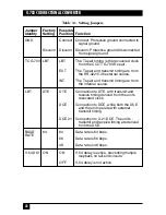
Prior to installing the G.703 Codirectional Converter, determine its
configuration in the data system and set its jumpers accordingly. Refer to
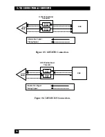
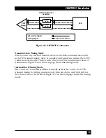
Table 3-1 on page 22. The diagrams in
Chapter 2
can help you identify the
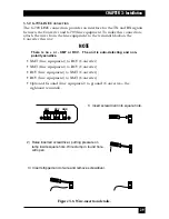
required jumper selection. Jumper locations on the printed circuit board are
shown in Figure 3-1 on the next page. Read the instructions in
Section 3.3.2
before making any changes.
Figure 3-1. Board layout of the G.703 Codirectional Converter.
NOTES
Be aware that in the drawing above, the jumpers are exaggerated in size
and other elements are minimized or deleted. For example, the JP1
jumper is in fact partially obscured by the interface module in the AC-
powered models. Also, in both AC- and DC-powered models, the “JP1”
label is partially or completely covered by material that helps secure the
board to the rear panel.
There is also a second element labeled “JP1” on the interface module
itself. Just like the other JP1, this element will also serve to connect
chassis ground to signal ground, but it isn’t a jumper. Rather, it is two
contact points that can be soldered together to form a permanent
connection. Be very certain that you will
always
want the grounds tied
common before you solder these points together.
LD1
LD2
LD3
LD4
LD5
LD6
SW4
SW3
SW2
SW1
JP1
AC
OUTLET
OFF
CHASS
INTERFACE
MODULE
ON
V
.54 DL
Y
JP2
48K
BAUD RA
TE
56K
64K
JP7
CONNECT
DISCONN
TC G.703 CONNECT T
O
JP6
JP5
LBT
EXE
INT
DCE21
DCE
DTE

