background image

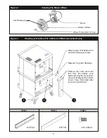
D.    LOCATION  AND  MINIMUM  CLEARANCES:

Move  the  oven  to  its  final  location  keeping  the  minimum  clearance  from  the  back  of  the  oven  to  the  wall.  This 
clearance  is  necessary  for  safe  operation  and  to  provide  proper  air  flow  to  the  burner  chamber.

MINIMUM  CLEARANCES  FROM  COMBUSTIBLE  AND  NONCOMBUSTIBLE  CONSTRUCTION


Under  Ventilation  Hood


Direct  Venting


RIGHT  WALL 

1” 

1” 

LEFT  WALL 

1” 

3” 

REAR  WALL 

3” 

3” 

E.    GAS  CONNECTION:

The  ovens  should  not  be  installed  on  the  same  gas  supply  line  with  space  heaters,  boilers  or  other  gas 
equipment  with  high  intermittent  demand.

The  installation  of  the  oven  must  conform  to  the  latest  local  codes  or 

National  Fuel  Gas  Code,  ANSI  Z223.1, 

Natural  Gas  Installation  Code,  CAN/CGA-B149.1,  or  the  Propane  Installation  Code,  CAN/CGA-B149.2.

The  appliance  must  be  isolated  from  the  gas  supply  piping  system  by  closing  its  manual  shut-off  valve 
during  any  pressure  testing  of  the  gas  supply  piping  system  at  test  pressures  equal  to  or  less  than  ½  psig 
(3.45kpa).  The  appliance  and  its  shut-off  valve  must  be  disconnected  from  the  gas  supply  piping  system 
during  any  pressure  testing  of  that  system  at  test  pressures  in  excess  of  ½  psig  (3.45kpa).

Use  a  pipe  joint  compound  that  is  resistant  to  the  action  of  liquefied  petroleum  gases  when  making  gas 
connections.  For  Propane  gas,  use  at  least  ½”  (13  mm)  pipe  or  tubing  with  a  5/8”  (16  mm)  inside  diameter. 
For  Natural  gas,  use  ¾”  (19  mm)  pipe.
The  gas  pressure  regulator  is  part  of  the  combination  valve  and  is  adjusted  to  yield  a  pressure  of  3.5”  water 
column  (9  mbar)  for  Natural  Gas.  If  the  oven  is  ordered  for  use  on  Propane  Gas  or  Butane,  the  pressure 
regulator  in  the  combination  valve  is  preset  at  the  factory  to  yield  a  pressure  of  10”  water  column  (25  mbar).


NOTE:

  No  external  regulator  is  required.

Gas  supply  pressure  in  the  European  Community  countries  should  be  as  below.

Gas  Type Supply  Pressure

Gas  Type Supply  Pressure

G20

20  mbar

G30

30  or  50  mbar  depending  on  country

G25

25  mbar

G31

30,  37,    or  50  mbar  depending  on  country

G20/25

20/25  mbar

A  separate  shut-off  valve  for  each  oven  must  be  provided.  It  should  be  as  close  as  possible  to  the  place 
where  the  gas  line  goes  into  the  oven.  It  must  be  located  such  that  it  is  easily  accessible.  When  stacking  with 
another  oven,  two  shut-off  valves,  one  for  each  of  the  two  ovens,  must  be  provided.

After  the  Gas  Supply  has  been  connected,  it  is  extremely  important  to  check  all  the  piping  for  leaks. 
Use  a  soap  and  water  solution  or  a  product  expressly  made  for  this  purpose.  Do  not  use  matches, 
candles  or  a  flame  and  so  forth  to  check  leaks  since  these  methods  are  extremely  dangerous.

4

CAUTION:

  Do  not  set  the  oven  with  its  back  flat  against  the  wall.  It  will  not  operate 

properly  unless  there  is  at  least  three  inches  breathing  space  behind  the  oven

!

!


Suitable  for  installation  on  combustible  floor  when  installed  with  legs  or  casters 
provided.

!

!

CAUTION: 

Do  not  store  combustible  items  or  materials  on  racks.

!

!

Summary of Contents for COB-G

Page 1: ...rous Instructions to be followed in the event you smell gas should be posted in a prominent location Obtain these instructions from your local gas supplier WARNING Initial heating of oven may generate smoke or fumes and must be done in a well ventilated area Overexposure to smoke or fumes may cause nausea or dizziness 1 FOR YOUR SAFETY Do not store or use gasoline or other flammable vapors and liq...

Page 2: ...current Gas Safety Installation and Use Regulations and the relevant Building Regulations IEE Regulations Detailed recommendations are contained in the British Standard Codes of Practice B S 6172 B S 5440 Part 2 and B S 6891 Your oven will be packed sitting on its bottom The skid may be left under the oven for convenience in further handling Unpack carefully avoiding damage to the Stainless Steel ...

Page 3: ...d Draft Hood must be placed into the hole on top of the oven C INSTALLATION WITH CASTERS OPTIONAL Refer to Figure 4 Four casters two with wheel brakes and the mounting hardware are packed and included in the shipment if ordered Install casters with wheel brakes on the front of the unit Installation of the unit should be made with a connector that complies with the latest edition of the Standard fo...

Page 4: ...ter For Natural gas use 19 mm pipe The gas pressure regulator is part of the combination valve and is adjusted to yield a pressure of 3 5 water column 9 mbar for Natural Gas If the oven is ordered for use on Propane Gas or Butane the pressure regulator in the combination valve is preset at the factory to yield a pressure of 10 water column 25 mbar NOTE No external regulator is required Gas supply ...

Page 5: ...orm to local municipal codes In the U K follow ventilation requirements as detailed in B S 5440 Optional direct venting not available for European community countries If direct venting a flue adapter and a draft hood are required to be installed They prevent the flue gases leaving the oven to be affected by the air pressure changes on the outside of the flue stack extending out of the building The...

Page 6: ...o increased efficiency of this oven the temperature of standard recipes may be reduced 50 F 30 C 3 Always load each shelf evenly Space pans away from each other and from sides and back of oven to allow maximum air flow between them 4 Large tempered glass windows and interior lights allow a close check on the product making it unnecessary to frequently open the doors Products cook faster in a conve...

Page 7: ...wer desired temperature follow the steps detailed below 1 Open the oven doors 2 Turn Selector Switch to oven cool down position Fan will now operate and cool down the oven 3 When the oven has cooled down to the desired temperature turn the Selector Switch to O position Close oven doors 7 CAUTION Use mild detergent or soap solution for best results Abrasive cleaners could scratch the finish of your...

Page 8: ...d rub cleanser on the metal in the direction of the polished lines on the metal Rubbing cleanser as gently as possible in the direction of the polished lines will not mar the finish of the stainless steel To remove discoloration use a non abrasive cleaner NEVER use a wire brush steel or abrasive scouring pads scraper file or other steel tools NEVER RUB WITHACIRCULAR MOTION D SERVICING NOTE THISAPP...

Page 9: ...t 3 8 Hex Blower Wheel Set Screws 2 Motor Cleaning The Blower Wheel Figure 2 Attach part 21818062 with 6 each 8 32 stainless screws Material 14 ga 201 Stainless Remove the outer and inner flue from the bottom oven before placing the top oven to prevent damaging the bottom oven s flue Re install after top oven is positioned 2 1 3 ...

Page 10: ...6 5 8435000 Hex Nut 5 16 18 6 82447 00 Hex Hd 3 8 16 X 750 5 Item P N Description 1 Attachtwoitem2totwoitem1usingitem3 4and5 2 Attachtwoitem7totwoitem1usingitem3 4and5 3 Using proper lifting equipment attach item 1 to the corresponding hole patterns located in the bottom oftheovenwithitem6 1 21796810 Weldment Oven Leg 2 8633102 Caster 5 Swivel W Top Plate 3 8227700 Hex Hd 5 16 18 X Bolt 5 Zn 4 850...

Page 11: ...UTTON SWITCH CH104 CONTROL COMBINATION VALVE GREEN LIGHT CENTRIFUGAL SWITCH FAN MOTOR MOT 35 COM 20 21 12 41 41 10 28 26 33 32 33 32 1 1 2 12 5 8 8 44 44 9 9 13 13 40 YELLOW BLUE BLACK WHITE 34 34 10 GROUND SWITCH 22 31 23 40 18 21 23 31 17 16 4 GROUND STUD GROUND STUD BUTT SPLICE 29 29 26 15 2 38 36 14 11 11 6 7 15 42 42 14 5 3 19 43 4 3 3 P3 1 2 P2 P1 4 P4 IGNITION CONTROL 18 FLAME SENSE GROUND ...

Page 12: ... LOW CENTRIFUGAL SWITCH FAN MOTOR COM 120V WHITE GROUND 24V 4 POS SWITCH T STAT LIGHT GROUND STUD GROUND STUD PROBE TRANSFORMER 13 12 2 32 33 15 15 2 31 33 23 22 6 12 7 14 6 1 11 3 9 4 14 5 39 36 38 16 17 32 10 4 13 28 8 29 21 18 19 37 23 COMBINATION VALVE 31 MOT 21 16 19 20 17 18 35 29 11 20 26 34 10 1 7 3 9 BUTT SPLICE L1 24VAC GROUND FLAME SENSE VALVE HOT THERMOSTAT IGNITOR 22 40 41 BUTT SPLICE...

Page 13: ...dering ALWAYS specify Part Model Serial Voltage Phase type of Gas Serial Number Voltage Phase 115 1 208 240 1 230 1 CE COB G COM G Full Size Gas Convection Oven PO Box 80400 Simpsonville SC 29680 0400 USA 864 963 3471 864 963 5316 800 927 6887 www bkideas com Phone Fax Toll Free Website ...

Page 14: ...E8765A Kit Conversion To LP E8766A Kit Conversion To Nat Part Description 1 33 0 34 5 4 12 2 3 30 8 10 11 28 29 9 32 31 27 17 26 20 19 24 7 22 18 13 25 21 14 15 16 23 39 44 45 37 47 74 73 67 50 49 40 46 48 85 84 81 63 62 61 56 60 83 52 54 68 70 55 43 42 72 53 35 38 41 76 82 78 75 79 80 64 56 65 77 66 58 57 59 51 69 36 87 86 88 89 90 6 71 91 1 4 5 92 6 7 9 10 20 19 18 17 16 15 14 13 11 80 79 78 77 ...

Page 15: ...acket Mounting Potentiometer Chain Roller 35 COM G Only Nut Hex Left Hand 1 4 20 S S COM G Only Nut Hex 1 4 20 S S COM G Only Probe RTD Direct Vent 1 2 3 4 5 6 7 8 9 10 11 12 13 14 15 16 17 18 19 20 21 22 23 24 25 26 27 28 29 30 31 32 33 34 35 36 37 38 39 40 41 42 43 44 45 46 E8189A E8138A M9208A S1195A E8160A S6810A M1102A E8170A E8178A E8177A E8176A E8156A E8193A M1332A M0110A E6895A M1352A P720...

Page 16: ...SIONS Negligence or acts of God Thermostat calibrations after 30 days from equipment installation date Air and Gas adjustments Light bulbs Glass doors and door adjustments Fuses Adjustments to burner flames and cleaning of pilot burners Tightening of screws or fasteners Failures caused by erratic voltages or gas supplies Unauthorized repair by anyone other than a BKI Factory Authorized Service Cen...

Reviews: