


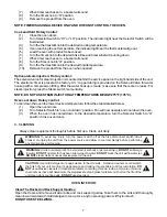


I. INSTALLATION INSTRUCTIONS
Section Item
Page
A
Receiving
2
B
Set Up / Mounting
2
C
Installation with Casters
(Optional)
3
D
Location & Minimum Clearances
4
E
Gas Connections
4
F
Electrical Connection
5
G
Flue Connection Ventilation
5
H
Burner Operation
5
I
System Check
Rotary Control
5
J
Programming Menus
6
II. OPERATING INSTRUCTIONS
A
General Instructions
6
B
Operation Sequence
Rotary Control
6
Cook only
Rotary Control
6
2
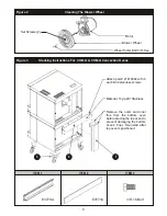
I. INSTALLATION INSTRUCTIONS
A. RECEIVING
Read the notice on the outside carton regarding damage in transit. Damage discovered after opening the
carton is “CONCEALED DAMAGE.” Carrier must be notified immediately to send an inspector and to
furnish forms for claims against the carrier.
When the oven arrives, it should consist of:
!
A crate or carton containing your new oven (two for a stacked unit).
!
A carton containing four 31” legs with mounting hardware (set of four 6” legs is supplied for stacked
installations).
!
A carton containing a Flue Adapter and a Draft Hood. Optional: for Direct Venting (Not available for
European Community Countries).
B. SET UP / MOUNTING:
NOTE:
This appliance must be installed by competent personnel in accordance with the rules in force.
In the U.K., Corgi registered installers (including the regions of British Gas) undertake to work to safe and
satisfactory standards. This appliance must be installed in accordance with the current Gas Safety
(Installation and Use) Regulations and the relevant Building Regulations/IEE Regulations. Detailed
recommendations are contained in the British Standard Codes of Practice B.S. 6172, B.S. 5440: Part 2 and
B.S. 6891.
Your oven will be packed sitting on its bottom. The skid may be left under the oven for convenience in further
handling. Unpack carefully, avoiding damage to the Stainless Steel front and/or trim. If concealed damage
is found, follow the instructions detailed in Section A (Receiving). Keep the area around the ovens free and
clear of combustible materials. Do not store any materials on top of or under any oven. The provision for
adequate air supply to your oven for ventilation and proper gas combustion is essential. As a minimum,
observe the clearances detailed in Section D (Location). Provide adequate ventilation and make up air in
accordance with local codes. Servicing your oven is done through the front control panel and right side
access cover. Ensure that these areas are kept unobstructed for easy access.
In MASSACHUSETTS:
All gas products must be installed by a “Massachusetts” licensed plumber or gas
fitter. Ventilation hoods must be installed in accordance with NFPA-96, current edition, with interlocks as
described in that standard.
INDEX
Section
Item
Page
Timed Cooking
Rotary Control
6
Cook and Hold
Rotary Control
7
Optional Steam Injection
Rotary Control
7
To Cool Down the Oven Quickly
7
C
Cleaning
7
D
Servicing
8
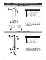
Stacking Instructions
9
Leg Assembly Instructions
10
Wiring Diagrams
11
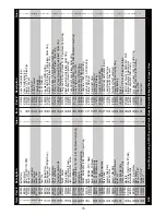
Parts List & Exploded View
13
Warranty
16


