background image


Installing your instrument


Place the spinit® instrument on a dry, clean, vibration

-

free and horizontal surface. Only use parts 

approved by biosurfit. The use of non

-

approved parts may result in malfunction of the instrument 

and may render the warranty null and void. 


Make sure it is in a well

-

ventilated environment, allowing at least 20 cm of free space at each side 

of the instrument.


Acclimate the instrument to ambient operating temperature (15

-

30°C).


The instrument might be impaired by:


• 

Condensing humidity and water


• 

Heat and large temperature variations


• 

Direct sunlight


• 

Vibrations (e.g. from centrifuges and dishwashers)


• 

Movement of the instrument during processing of a Test 


Connecting power supply


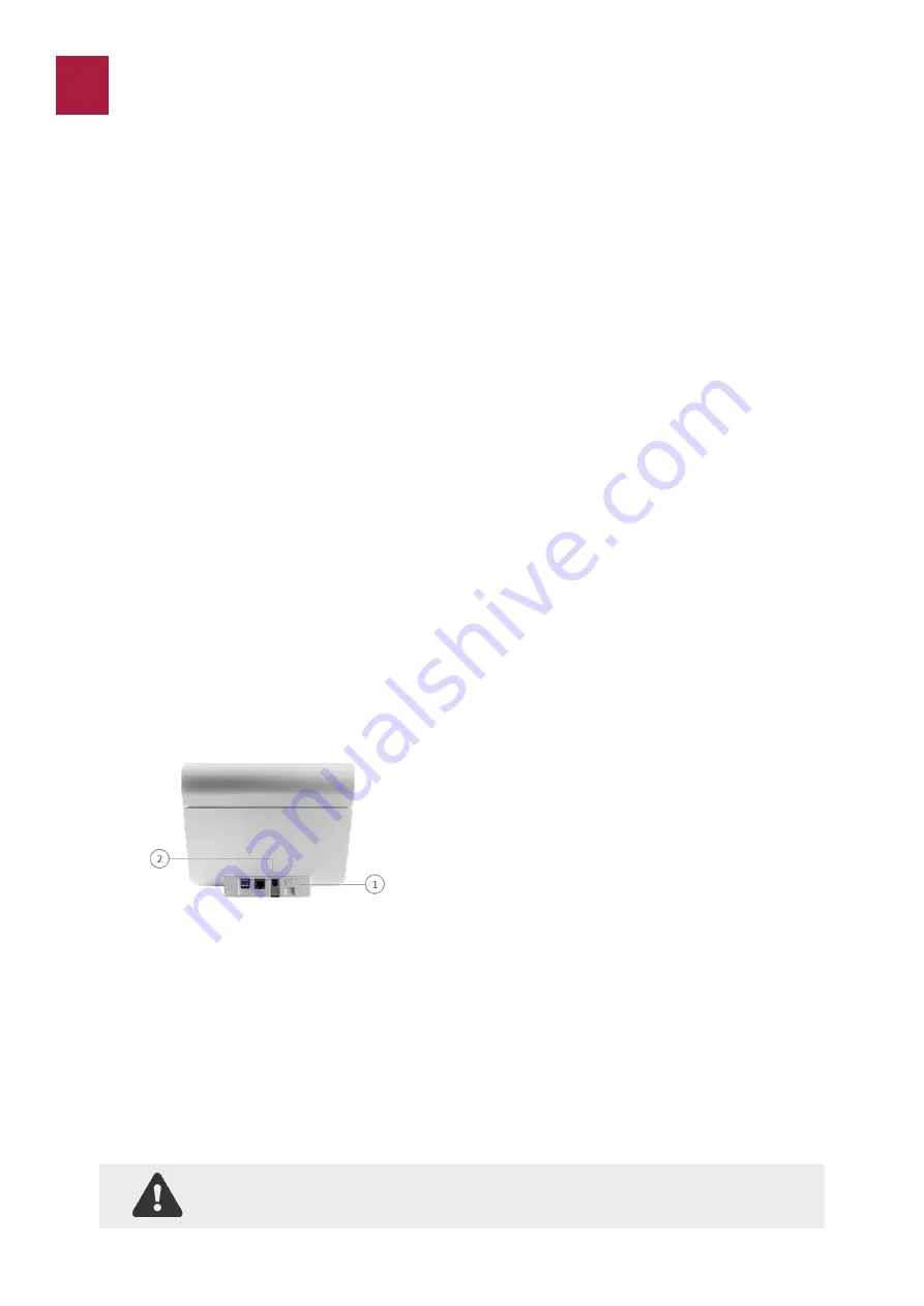
Connect the power supply cable to the power supply unit (Figure 3). 


Insert the plug from the power supply cable into the power socket in the back of the instrument. 


Connect the instrument to grounded power outlets only. 


Always  use  the  correct  supply  voltage.  The  power  supply  voltage  must  match  the  information 
quoted in the section Technical specifications, page 35.


1.


Power ON button. 


2.


Power input for power supply connection. 


Connecting additional equipment


Optional equipment not provided with your spinit® instrument are:


• 

Printer –


for optional print out of test results.


For  additional  information  regarding  the  barcode  reader,  printer,  and  connection  to  HIS  or  LIS    
systems, please contact your local spinit® instrument supplier.


 Connecting the equipment should be done while the instrument is powered off. 


Figure 3. 


spinit® User Manual | 

Getting Started


GETTING STARTED


Summary of Contents for spinit E40

Page 1: ...English User Manual spinit S40 spinit E40...

Page 2: ...control 7 Getting Started 8 Installing your instrument 8 Connecting power supply 8 Connecting additional equipment 8 How to turn ON the instrument 9 How to turn off the instrument 9 How to operate the...

Page 3: ...3 Operating Precautions 23 Preparing for sample analysis 23 Prepare for testing patient samples 24 Prepare for testing quality Control material 26 Info Codes and Troubleshooting 30 Service Information...

Page 4: ...of the instrument Do not spill any liquids or drop any objects onto or into the spinit instrument The spinit instrument should not be near or in contact with water Spillage of potentially infectious m...

Page 5: ...rovisions in the European directive 98 79 EC on In Vitro Diag nostic Medical Devices and is CE marked accordingly Safety standards The spinit instrument has been tested and found to be in conformity w...

Page 6: ...of the test procedures and contains information on proper quality control routines We recommend that you become familiar with the user instructions before you start operating the spinit instrument Un...

Page 7: ...ch screen spinit instrument user interface operated by touching virtual buttons on a colored touchscreen 6 Tray The tray protects the instrument and the disc from dust light and humidity while per for...

Page 8: ...scs The spinit disc is unique for each analyte to be measured and integrates test specific reagent compositions and volumes The spinit discs have a unique color for each test and are separately packed...

Page 9: ...function as detectors and an electronic circuit board that processes the LEDs independently Emitted light is reflected inside the disc and passes through a detection chamber Transmittance of light thr...

Page 10: ...h each patient test result in the results panel Operator ID The spinit operator function will if configured allow the operators to insert their identification before testing The operator ID will be st...

Page 11: ...cting power supply Connect the power supply cable to the power supply unit Figure 3 Insert the plug from the power supply cable into the power socket in the back of the instrument Connect the instrume...

Page 12: ...ment The instrument is easily operated using the touch buttons that appear on the screen When a button is touched its function will be activated Text messages that appear on the screen will help guide...

Page 13: ...10 spinit User Manual Getting started Figure 4 1 Text message 2 Touch buttons 3 Tray with a ready to use disc Sound signals A short beep indicates completion of an analysis...

Page 14: ...spinit User Manual Configuration 11 The spinit menus Different configurations are available in the spinit settings menu namely retrieval of past results language selection HL7 connection status acces...

Page 15: ...must click on HL7 Status button It will provide information regarding network connectivity HL7 configuration status of the device and the number of HL7 messages that the system was unable to send to t...

Page 16: ...tablished acceptable ranges for spinit instrument Results are then shown in the standard format with the indication of Quality control The user may later view print or transfer information on all prev...

Page 17: ...ser management create and delete new users and erase data Data On the menu Data the system Admin has the possibility to define if results can be sorted without a password To export data connect the US...

Page 18: ...control results records page 13 To add an Operator select Operators on the Advanced settings menu Press Add to enter letters numbers or scan with your ID Press Enter to confirm and select Back to go t...

Page 19: ...After se lecting the units click Apply All test results will be calcu lated and shown in the selected units This setting may be changed anytime The results stored in the instrument will be shown in th...

Page 20: ...assword on the Advanced Settings menu press the button Change Password type a new password and click Next Configure printer The user shall connect the printer while the spinit instrument is turned off...

Page 21: ...to send information to the LIS HIS The connectivity settings can be defined in the HL7 Config menu in the Advanced Setting menu In order to enable this feature as well as the Order Material Request OR...

Page 22: ...n make a Hardware check where it will be possible to verify the internal spinit hardware status regarding cameras and hardware On spinit instrument data it is possible to export files through a USB pe...

Page 23: ...errors are detected Retest the control material using a new control vial Examine the laboratory s quality control record to investigate the frequency of control fail ures Patient samples should not b...

Page 24: ...obtained After installing each software update When training new operators in correct use of the spinit instrument In compliance with national or local regulations The controls should always be analyz...

Page 25: ...s Do not use the disc if the foil pouch or the disc itself is damaged The disc must reach recommended operating temperature 15 30 C before use Do not open the foil pouch until just before use Once ope...

Page 26: ...cted Allow 5 minutes for the test disc to reach operating temperature if applicable 15 30 C before use Press Start and follow on screen instructions Read spinit disc barcode you want to test Press the...

Page 27: ...sample area is fully loaded If not discard the strip and use a new one Immediately insert the strip all the way into the disc and fold it back until it breaks Leave the loaded part of the strip insid...

Page 28: ...le Open the foil pouch remove the disc and place it on a flat surface with label facing up Discard the foil pouch in suitable waste containers Inspect the disc Do not use it if it is damaged Extract t...

Page 29: ...ell Test analysis must start immediately after loading the disc Discard the strip s handling area accordingly spinit User Manual Testing Procedure 29 Once you have the disc ready click Next on the scr...

Page 30: ...ence to information codes or messages GENERAL SYSTEM MALFUNCTION CAUSE SOLUTION spinit does not start Power supply inadequately con nected Connect power supply Start up procedure failed Contact your l...

Page 31: ...g a new disc as per Instructions for Use If the problem persists please contact your local supplier 208 Disc spinit disc microfluids com promised due to incorrect flows of fluids within the disc Colle...

Page 32: ...nics Shutdown the device and unplug it from the power supply for 10 seconds Restart the device and repeat the test using a new test disc as per Instructions for Use If the problem persists please cont...

Page 33: ...t the test using a new spinit BC disc as per Instructions for Use If the problem persists please contact your local supplier 1002 Disc Sample Sample processing is com promised likely due to in complet...

Page 34: ...m the date of delivery The manufacturer agrees to repair or replace the instrument if it becomes inoperative due to the failure of any internal parts The war ranty does not cover damage caused by use...

Page 35: ...cm Weight 4 1 kg Display Standard LCD color display with back light and integrated touch panel Resolution 240 x 320 pixels Visible area 58 x 77 mm Capacity of result records 100 000 Capacity of operat...

Page 36: ...ters The design development and manufacturing of the spinit instrument is in accordance with bio surfit Quality Management System ISO13485 certified company For further detailed information on technic...

Page 37: ...the spinit system Symbol Explanation CE marking of conformity to directive 98 79 EC on in vitro diagnostic medical devices Manufacturer s name and address In vitro diagnostic medical device Serial Nu...

Page 38: ...Rua 25 de Abril n 66 2050 317 Azambuja Portugal ISO13485 certified company vww biosurfit com PL 006 05 EN REV 03 03 2020...

Reviews: