4
spinit® User Manual
|
spinit® system description
Do not open or close the tray manually.
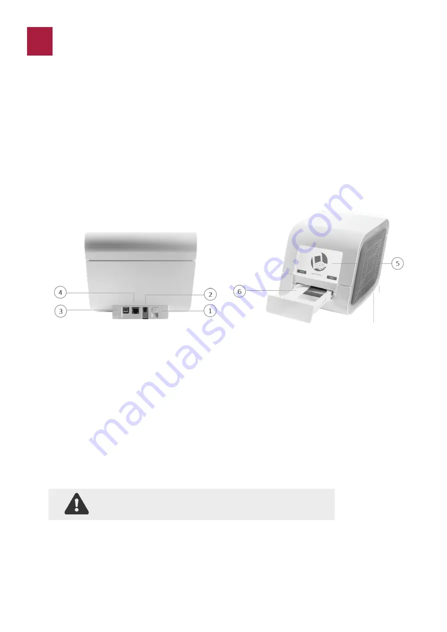
Description of the spinit® instrument
Figure 1.
1.
Power ON button
2.
Connection to power supply;
3.
Two (2) USB ports: to connect an external printer, a barcode reader or a USB pen drive. The
USB pen drive can be used to export data and upload software updates;
4.
RJ
-
45 connector to Ethernet cable (LAN port is considered as in house SELV): connectivity
option to remote Laboratory or Hospital Information System (LIS/HIS);
5.
Touch screen
-
spinit® instrument user interface operated by touching virtual buttons on a
colored touchscreen;
6.
Tray: The tray protects the instrument and the disc from dust, light and humidity while per-
forming an assay and when the instrument is not in use;
The spinit® instrument is a stand
-
alone, small benchtop medical device with a user friendly interactive
touchscreen and an automatic tray designed to accommodate any spinit® disc. Figure 1 shows the
main exterior parts of the spinit® instrument.
The spinit® System
The spinit® system includes the spinit® instrument, spinit® discs, spinit® controls and spinit® strips.
All components were designed and developed to be used exclusively.
spinit® SYSTEM DESCRIPTION


