background image

Part No. 400988                                                                                                                                                                     Form No. F010496B

EU Distributor

List   900774

EU Declaration

of Conformity

400989

EU Declaration

of Conformity

Page 4 of 8

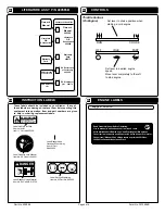
These labels should be included on your Blower.  If any of
these labels are damaged, replace them before putting this
equipment into operation. Item and part numbers are given
to help in ordering replacement labels.

INSTRUCTION LABELS

ENGINE LABELS

12

12

12

12

12

15

15

15

15

15

Read Owner’s Manual Before Operating.

Lire le manuel d’utilisation avant la mise en route.

Vor Inbetriebnahme Bedienungs - und  Wartungsanleitung lesen.

Favor leer las instrucciones de operacion antes de operar el motor.

Consultare il Manuale Uso e Manutenzione prima dell utilizzo.

Las Skotselinstruktionen Innan Start.

'

'

'

..

..

Briggs & Stratton

14

14

14

14

14

Label Do Not Fill While
Engine Is Hot
Item 11  Part No.400268

EXPLOSIVE FUEL

STOP ENGINE AND ALLOW TO
COOL BEFORE REFUELING.

400268

WARNING

Label Danger Keep
Hands and Feet Away
Item 41 Part
No.400424

Label Read Owner's Manual
Item No. 59  Part No. 890301

DANGER

810736

Label Danger Flying Material
Item No. 44  Part No. 810736

890254

Label Ear Eye Breathing
Item No. 63 Part No. 890254

LITERATURE ASSY  P/N 400565B

Check

Owner's

Manual

400988

Literature Checklist

Owner's

Manual

CONTROLS

13

13

13

13

13

Throttle Control-
(On Engine)

RUN

OFF

CHOKE

IDLE

FAST

Set lever to choke position when
starting a cold engine

Set lever to desired engine
speed.
Move lever completely to the left
to stop engine

Literature

QB

Accessories

400908

Check

Check

Warranty

Card

400972

Check

Literature

QB

Accessories

Warranty

Card

EU Distributor

List

Check

Summary of Contents for QUIET BLOW QB501CE

Page 1: ... areas around buildings and shrubbery GUST ADJUSTER KIT GUST ADJUSTER KIT GUST ADJUSTER KIT GUST ADJUSTER KIT GUST ADJUSTER KIT P P P P P N 400615 N 400615 N 400615 N 400615 N 400615 Increases blowing distance and blowing control CREVICE CLEANER KIT CREVICE CLEANER KIT CREVICE CLEANER KIT CREVICE CLEANER KIT CREVICE CLEANER KIT P N 400620 P N 400620 P N 400620 P N 400620 P N 400620 Cleans out crac...

Page 2: ...operate engine with an accumulation of grass leaves dirt or other combustible material in the muffler area 2 0 DO NOT DO NOT DO NOT DO NOT DO NOT use this engine on any forest covered brush covered or grass covered unimproved land unless a spark arrester is installed on the mu f f l e r The arrester mu s t be maintained in effective working order by the opera t o r I n t h e S t a t e o f C a l i ...

Page 3: ...pletely assembled except for the upper handle assembly These items should be included in your carton If any of these parts are missing contact your dealer 17 Boxing Checklist Check Literature Assy 400565B Per Model Check Briggs Stratton 5 HP Per Model P N MS9249 Multi Language Handle Upper Assembly 400957 Literature Assy Engine Manual DO NOT direct exhaust outlet toward any bystanders DO NOT opera...

Page 4: ...as Skotselinstruktionen Innan Start Briggs Stratton 14 14 14 14 14 Label Do Not Fill While Engine Is Hot Item 11 Part No 400268 EXPLOSIVE FUEL STOP ENGINE AND ALLOW TO COOL BEFORE REFUELING 400268 WARNING Label Danger Keep Hands and Feet Away Item 41 Part No 400424 Label Read Owner s Manual Item No 59 Part No 890301 DANGER 810736 Label Danger Flying Material Item No 44 Part No 810736 890254 Label ...

Page 5: ...is can be effectively blown into a consolidated area for convenient pickup and removal BLOWING OPERATION 16 2 16 2 16 2 16 2 16 2 Adjust diverter rod to side discharge for normal blowing or to forward discharge for blowing along walls fences or hard to reach areas see Fig 1 ENGINE See engine manufacturer s instructions for type and amount of oil and gasoline used Engine must be level when checking...

Page 6: ...Part No 400988 Form No F010496B Page 6 of 8 R PARTS DRAWING QB501CE QB501CE QB501CE QB501CE QB501CE 18 18 18 18 18 ...

Page 7: ...K 5 16 18 THIN HT 8161041 1 34 SCREW CAP 5 16 24 NF x 3 4 8042026 2 35 36 37 38 WASHER 0 765 1 0 x 1 25 OD x 0 06 850238 2 39 NUT LOCK 10 24 8164005 2 40 DEFLECTOR 400333 1 41 LABEL DANGER HANDS FEET 400424 1 42 BOLT CARRIAGE 5 16 18 x 1 3 4 8024043 1 43 WASHER FLAT 3 4 S A E 3 16 x 1 1 2 x 1 8 8172015 2 44 LABEL DANGER FLYING MATERIAL 810736 1 45 WASHER 3 4 HUB CAP 850237 2 46 GRIP 400570 2 47 KN...

Page 8: ...ble gear or wheel puller against the bolt head and the impeller back plate near the blades remove impeller from shaft 8 Reinstall new impeller in reverse order of removal 9 Tighten impeller bolt Torque impeller bolt see parts list on page 7 for proper impeller bolt torque specifications 20 20 20 20 20 IMPELLER REMOVAL 17 2 17 2 17 2 17 2 17 2 Engine See Engine Manual Check for excessive vibration ...

Reviews: