background image

EX200 Electro-Hydraulic Actuator Positioner 


Bifold Orange Limited. 


Drwg. No.: ORM0001     Issue : 1    Date : 24/06/2015          Page : 

6 of 20 


The solenoid sense and command signal default mode are set up by internal jumper links according to the part number 
selected during ordering.    Check the accompanying Certificate of Calibration/Conformity for the factory setting of the 
jumper links.   If a change is required, then the top cover of the instrument has to be removed to access the links: 
 

1)  If the instrument is difficult to access, make a note of the wiring, disconnect and remove the EX200 from its 

enclosure. 

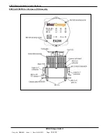
2)  If the unit is housed with the EXD2010 Ex d enclosure ensure that there is no hazardous atmosphere present and 

remove the lid from the EXD2010 Ex d enclosure. 

3)  Work in a clean, dry area and use electrostatic discharge protection equipment - a wrist strap and a grounded 

work mat to make the changes. 

4)  Unscrew the two M2.5x5 screws from the top of the instrument. 
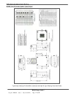
5)  For the Din Rail Mount enclosure, gently push in one of the black fixing lugs on the side of the top cover and 

remove the cover. 

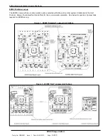
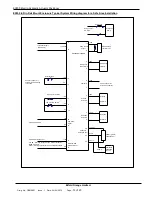
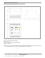
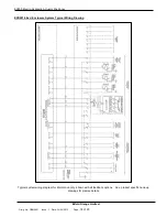
6)  Check with the layout drawings on page 4, Figure 1 for Standard communication, Figure 2 for Hart 

Communication, for position of jumper links on the base printed circuit board and make the necessary changes.   
Note that ONLY one selection, + or -, MUST be made for each of the output blocks - LINC LDEC LESD LFLT 
even if the fault or ESD outputs are not used.  

7)  Double check and record the selection then reverse the above procedure to reassemble the EX200. 

 
Setting solenoid operating sense 

If the actuator has a spring assisted return to a default position it may be necessary to change the sense of the output 
solenoid such that at the desired balance point one of the solenoids is energised thus holding the actuator position 
against the spring.  Follow the procedure described in Positioner set-up above and select between LDEC +/- and LINC +/- 
links for the required solenoid sense.    
 
The default EX200 supply is for a double acting actuator, to select a factory set unit for a spring to close actuator please 
add “SC” where indicated in the part number selection chart, and for spring to open add “SO”. 
 

Setting retransmitted actual position signal drive type 

– Sourcing or Sinking 

Links SO and SI can select the excitation for the retransmitted actual position signal.   Link SO selects INTERNAL 12V 
excitation and Link SI selects EXTERNAL 12-30V excitation.  Only select ONE excitation drive type.  For the EX200 with 
Hart communication option, link both SO or both SI links.   
 
The default EX200 supply is for a sourcing retransmitted signal, to select a factory set unit for a sinking retransmission 
add “SK” where indicated in the part number selection chart.   

 
Setting the auxiliary solenoid and fault output sense 

These two outputs can respond to failures in the control signals to the system and an external fault input.  The EX200 
normally sets these two outputs as energised when healthy but the sense of the outputs can be reversed by following the 
procedure described in Positioner set-up above and selecting between LESD +/- (auxiliary solenoid) and LFLT +/- (fault 
output) links for the required outputs.   The LESD auxiliary output is linked to the OK light on the front of the EX200 

 
Setting the command signal break default operation 

In the event of a command or feedback signal break or, if selected, an external fault, then the actuator can be forced to 
one of three default conditions - freeze operation, drive down or drive up.  These faults are characterised as: 
 
     a) the command falling below 1mA - command signal break 
     b) the potentiometer wiper showing less than 0.25V - potentiometer maximum or wiper break 
     c) the potentiometer wiper showing more than 4.7V - potentiometer minimum break.   
 
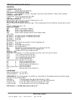
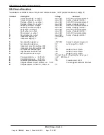
For the EX200 with “Standard” Communication option follow the procedure described in Positioner set-up above and 
select from positions A and B on link block LK1 as follows: 


Function 


Out 

Out 

Freeze mode on signal fault 


In 

Out 

Drive down on signal fault 


Out 

In 

Drive up on signal fault 


In 

In 

Freeze mode again 


For the EX200 with “Hart” Communication these are set on power up and not using links as per the above.  A one-off 
operation of the positioner will store the choice in non-volatile EEPROM memory. 

Summary of Contents for EX200

Page 1: ...EX200 ELECTRO HYDRAULIC ACTUATOR POSITIONERS Operation Installation and Maintenance Manual ...

Page 2: ...ing option timers 7 Setting the HART private command enable and remote slow fast operation 8 First time operation 9 Calibration 9 Normal operation fault detection 9 Self contained operation 10 Maintenance 10 EX200 H Hart Version HART Revision 7 16 bit Manufacturers and Device ID 11 HART Command Summary 11 Universal Commands 11 Common Practice Commands 11 Private Commands 11 Specification 13 EX200 ...

Page 3: ...rol of the position driver including electro hydraulic actuators and reversing ac motors with the addition of suitable relays contactors or motor control equipment The EX200 can accept positional feedback from a three wire potentiometer or a position transducer with a current output All signals and power supplies are referenced to power supply zero ensuring safe connection to centralised digital c...

Page 4: ...mounted polyester enclosure measuring 85 x 70 x 58h The circuit boards are coated with a resist layer that protects the track from moderate condensation and mould growth problems Connections are via screw terminals with a capacity of 2 5mm 2 but the use of ferrules or crimps is recommended All adjustments are accessible on the front panel of the enclosure Initial configuration adjustments are via ...

Page 5: ... up The EX200 comes with two communication options selected within the part number system Standard and the Hart Protocol Setup of instrument functions differs for this communication selection See below for position of jumper links required for EX200 set up Figure 1 EX200 Standard Jumper Link Options Figure 2 EX200 Hart Jumper Link Options ...

Page 6: ...lect a factory set unit for a spring to close actuator please add SC where indicated in the part number selection chart and for spring to open add SO Setting retransmitted actual position signal drive type Sourcing or Sinking Links SO and SI can select the excitation for the retransmitted actual position signal Link SO selects INTERNAL 12V excitation and Link SI selects EXTERNAL 12 30V excitation ...

Page 7: ...only triggers fault output In External fault triggers fault output auxiliary solenoid output and instrument default mode For the EX200 with Hart Communication option this is changed via HART in Command 129 81h Setting the self contained pump control options The EX200 has an output to control a hydraulic pump supplying power to the actuator The pump can be configured to operate on demand when a cha...

Page 8: ...gured to enable disable reception of a private command used to remotely set the pulsing mode timers and the dead zone The procedure also allows local resetting of the HART command allowing local adjustment of stepping times and selection of continuous or stepping operation should HART communications fail 1 Hold in the CALIBRATE pushbutton and apply power to the positioner 2 Release the CALIBRATE p...

Page 9: ...mA command signal This must be the position the INC solenoid will drive the actuator to 7 Set the command signal to 20mA 8 Adjust the CAL1 potentiometer to give the required output for the chosen position Note that this not need be 20mA to match the command signal but can be any value in the range 0 5mA to 22mA 9 Press and hold the CALIBRATE button until the CALIBRATE LED goes out Release the butt...

Page 10: ... The unit must be left for 30 minutes with power off before the cover is removed To maintain an IP66 environmental rating after removing the Ex d enclosure cover the male threads of the enclosure should be liberally coated with Molykote BR2 Plus grease Please contact Bifold Orange if you have difficulty in sourcing this material The cover should be tightened sufficiently such that the cover to bod...

Page 11: ...he positioners The body of the message is 11 bytes Command 128 80h Device Specific Command Read positioner parameters Received Data None Response Data 0 1 INC off time H L 2 3 Dec off time H L 4 5 INC on time H L 6 7 DEC on time H L 8 9 Dead zone H L 10 Remote enable byte Command 129 81h Device Specific Command Write positioner parameters Received Data 0 1 INC off time H L 2 3 Dec off time H L 4 5...

Page 12: ...tepping mode via DIL switch position 4 factory default Bit 3 Set stops the actuator and ignores changes in command signal if Bit 1 is set Clear positions to command signal factory default Bit 4 Set Drives actuator down if Bit 1 is set Clear positions to command signal factory default Bit 5 Set Drives actuator up if Bit 1 is set Clear positions to command signal factory default Note only one of bit...

Page 13: ...h 2 No function DIP Switch 3 Select stepping mode timers DIP Switch 4 Select stepping mode DZ Potentiometer to set positioning dead zone clockwise to increase CAL1 Calibration adjustment and ON time for stepping mode CAL2 Adjustment for OFF time for stepping mode INTERNAL LINKS Output sense one position or must be selected for each output even if the output is unused LINC and Increase solenoid sen...

Page 14: ...to 0V to energise output 8 Fault output ve output max 36V Always at supply potential 9 Pump output ve output max 36V Set to 0V to energise output 10 Pump output ve output max 36V Always at supply potential 11 Instrument Supply ve 15 to 36V 12 Instrument Supply 0V 0V 13 Actual position signal ve 12V 30V Scaled to actuator movement 14 Actual position signal ve 0V set in range 0 5 22mA 15 Instrument ...

Page 15: ...k Potentiometer Decrease Solenoid 200R or greater Feedback Pot Alternative Device 4 20mA EX200 POSITIONER 0 5 22mA Actual Position 2 Solenoid Increase 1 Solenoid Increase 9 Output Pump control 24V 10 External relay contactor coil Pump supply AC or DC Pump fuse Hydraulic Pump 24V dc open drain active when healthy 16 17 18 15 19 5V 5V 5V 0V 0V External fault High pressure switch Low pressure switch ...

Page 16: ...osure Dimensions and Front Panel Size 70mm wide 58mm high 85mm deep Weight 0 25kg Enclosure Lexan Top cover Noryl Base section Equipment rating IP40 The EX200 in the din rail mount enclosure can be fitted on Standard Symmetric EN50054 component mounting rail 35 x 7 5 Use a purpose designed tool for adjusting small potentiometers on the front panel ...

Page 17: ... Positioner Bifold Orange Limited Drwg No ORM0001 Issue 1 Date 24 06 2015 Page 17 of 20 EXD2010 Ex d Enclosure System Typical Layout Typical layout drawing for information only See product specific layout drawings for precise details ...

Page 18: ...e Limited Drwg No ORM0001 Issue 1 Date 24 06 2015 Page 18 of 20 EXD2010 Ex d Enclosure System Typical Wiring Drawing Typical system wiring diagram for information only shown with all feedback options See product specific hook up drawings for precise details ...

Page 19: ...EX200 Electro Hydraulic Actuator Positioner Bifold Orange Limited Drwg No ORM0001 Issue 1 Date 24 06 2015 Page 19 of 20 EX200 in EXD2010 Ex d Enclosure PCB Assembly ...

Page 20: ...t must be installed by skilled electricians or instructed personnel in accordance with National Legislation and relevant technical standards The equipment must NOT be operated in Zone 0 hazardous area The technical data listed on the enclosure label must be observed Changes to the design of the equipment are not permitted The equipment shall only be operated as intended and only in an undamaged co...

Reviews: