

EX200 Electro-Hydraulic Actuator Positioner
Bifold Orange Limited.
Drwg. No.: ORM0001 Issue : 1 Date : 24/06/2015 Page :
15 of 20
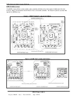
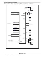
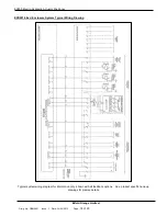
EX200 in Din Rail Mount Enclosure Typical System Wiring diagram for a Safe Area Installation
+
-
11
12
15-36Vdc
4-20mA Command
20
21
13
14
+12V
-
4
3
7
-
8
5
-
6
Emergency
Instument Supply
22
23
24
+5V max
Wiper
0V min
Emergency
solenoid O/P
Fault O/P
Decrease
Solenoid
Command
Signal
Retransmitted
Position Signal
Feedback
Potentiometer
Decrease
Solenoid
200R or greater
Feedback Pot.
+
-
Alternative
Device
4-20mA
EX200 POSITIONER
0.5-22mA Actual Position
2
Solenoid
Increase
-
1
Solenoid
Increase
-
9
Output
Pump control
+24V
10
External relay/
contactor coil
Pump supply
AC or DC
Pump fuse
Hydraulic
Pump
24V dc open drain
active when healthy
16
17
18
15
19
+5V
+5V
+5V
0V
0V
External fault
High pressure switch
Low pressure switch
+24V
+24V
+24V
+24V
solenoid
+5V
0V
0V
(max. 55mA)
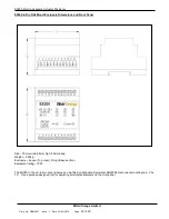
Connect 15 and 19 if
external fault monitoring
is not used
Feedback
Link SO - Sourcing output with 12V internal excitation
(400R max load)
Link SI - SInking output with 12-30V external excitation


