

EX200 Electro-Hydraulic Actuator Positioner
Bifold Orange Limited.
Drwg. No.: ORM0001 Issue : 1 Date : 24/06/2015 Page :
2 of 20
Contents
EX200 - ELECTRO-HYDRAULIC ACTUATOR POSITIONERS ............................................................................................................... 1
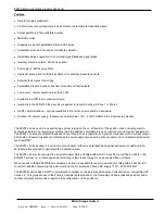
Features .......................................................................................................................................................................................................................... 3
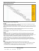
EX200 Part Number Selection Chart .............................................................................................................................................................................. 4
Operation......................................................................................................................................................................................................................... 4
Physical ........................................................................................................................................................................................................................... 4
Wiring .............................................................................................................................................................................................................................. 4
EX200 Positioner set-up ................................................................................................................................................................................................. 5
Setting solenoid operating sense .............................................................................................................................................................................. 6
Setting retransmitted actual position signal drive type
– Sourcing or Sinking ...................................................................................................... 6
Setting the auxiliary solenoid and fault output sense .............................................................................................................................................. 6
Setting the command signal break default operation .............................................................................................................................................. 6
Setting the auxiliary solenoid and fault output interlock ......................................................................................................................................... 7
Setting the self-contained pump control options ..................................................................................................................................................... 7
Setting the stepping option timers ............................................................................................................................................................................ 7
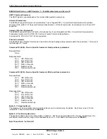
Setting the HART private command enable and remote slow/fast operation ......................................................................................................... 8
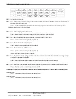
First time operation ........................................................................................................................................................................................................ 9
Calibration ....................................................................................................................................................................................................................... 9
Normal operation - fault detection ................................................................................................................................................................................. 9
Self contained operation .............................................................................................................................................................................................. 10
Maintenance .................................................................................................................................................................................................................. 10
EX200/H Hart Version - HART Revision 7 + 16 bit Manufacturers and Device ID...................................................................................................... 11
HART Command Summary ...................................................................................................................................................................................... 11
Universal Commands ............................................................................................................................................................................................... 11
Common Practice Commands ................................................................................................................................................................................. 11
Private Commands ................................................................................................................................................................................................... 11
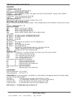
Specification ................................................................................................................................................................................................................. 13
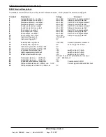
EX200 Terminal Descriptions ....................................................................................................................................................................................... 14
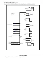
EX200 in Din Rail Mount Enclosure Typical System Wiring diagram for a Safe Area Installation ........................................................................... 15
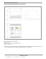
EX200 in Din Rail Mount Enclosure Dimensions and Front Panel ............................................................................................................................. 16
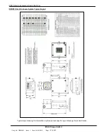
EXD2010 Ex d Enclosure System Typical Layout ....................................................................................................................................................... 17
EXD2010 Ex d Enclosure System Typical Wiring Drawing......................................................................................................................................... 18
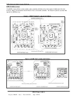
EX200 in EXD2010 Ex d Enclosure PCB Assembly .................................................................................................................................................... 19
EXD2010 Enclosure Assembly ..................................................................................................................................................................................... 20
Manufacturer and Approvals Details ....................................................................................................................................................................... 20
Instructions for Safety ............................................................................................................................................................................................. 20


